82C59A
This modification forces the use of software programming to release the device routine address during bytes 2 and 3 of
determine whether the 82C59A is a master or a slave. Bit 3 INTA. (Byte 2 only for 80C86/88/286).
in ICW4 programs the buffered mode, and bit 2 in lCW4
The cascade bus lines are normally low and will contain the
determines whether it is a master or a slave.
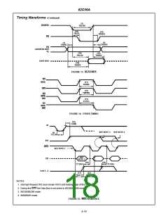
slave address code from the leading edge of the first INTA
pulse to the trailing edge of the last INTA pulse. Each
82C59A in the system must follow a separate initialization
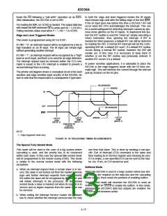
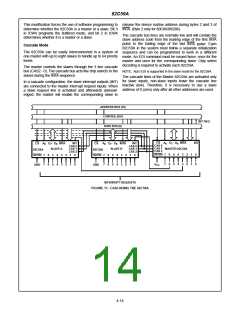
Cascade Mode
The 82C59A can be easily interconnected in a system of
one master with up to eight slaves to handle up to 64 priority
levels.
sequence and can be programmed to work in a different
mode. An EOI command must be issued twice: once for the
master and once for the corresponding slave. Chip select
decoding is required to activate each 82C59A.
The master controls the slaves through the 3 line cascade
bus (CAS2 - 0). The cascade bus acts like chip selects to the
slaves during the INTA sequence.
NOTE: Auto EOI is supported in the slave mode for the 82C59A.
The cascade lines of the Master 82C59A are activated only
for slave inputs, non-slave inputs leave the cascade line
inactive (low). Therefore, it is necessary to use a slave
address of 0 (zero) only after all other addresses are used.
In a cascade configuration, the slave interrupt outputs (INT)
are connected to the master interrupt request inputs. When
a slave request line is activated and afterwards acknowl-
edged, the master will enable the corresponding slave to
ADDRESS BUS (16)
CONTROL BUS
DATA BUS (8)
INT REQ
CS
A
D
- D INTA
INT
CS
A
D
- D INTA
INT
CAS 0
CAS 1
CAS 2
CS
A
D
- D INTA
INT
CAS 0
CAS 1
CAS 2
0
7
0
0
7
0
0
7
0
CAS 0
CAS 1
CAS 2
SLAVE A
SLAVE B
MASTER 82C59A
82C59A
SP/EN
82C59A
SP/EN
SP/EN
7
6
5
4
3
2
1
1
0
0
7
6
5
4
3
2
2
1
0
7
6
5
4
3
2
2
1
0
7
6
5
4
3
2
7
6
5
4
3
1
0
7
6
5
4
3
1
0
V
GND
GND
CC
INTERRUPT REQUESTS
FIGURE 11. CASCADING THE 82C59A
4-14

 INTERSIL [ Intersil ]