LXT971A 3.3V Dual-Speed Fast Ethernet Transceiver
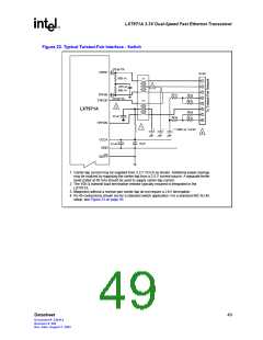
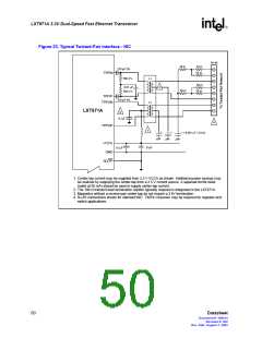
Figure 22. Typical Twisted-Pair Interface - Switch
270 pF 5%
TPFIP
RJ-45
50Ω 1%
1:1
1:1
1
2
3
4
5
6
7
8
0.01 µF
3
50Ω 1%
270 pF 5%
2
TPFIN
50
50
Ω
50
50
Ω
Ω
TPFOP
LXT971A
50
50
Ω
Ω
0.1µF
Ω
TPFON
1
* = 0.001 µF / 2.0 kV
*
*
4
VCCA
GND
.01µF
0.1µF
SD/TP
1. Center-tap current may be supplied from 3.3 V VCCA as shown. Additional power savings
may be realized by supplying the center-tap from a 2.5 V current source. A separate ferrite
bead (rated at 50 mA) should be used to supply center-tap current.
2. The 100 Ω transmit load termination resistor typically required is integrated in the
LXT971A.
3. Magnetics without a receive pair center-tap do not require a 2 kV termination.
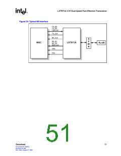
4. RJ-45 connections shown are for a standard switch application. For a standard NIC RJ-45
setup, see Figure 23 on page 50.
Datasheet
49
Document #: 249414
Revision #: 002
Rev. Date: August 7, 2002

 INTEL [ INTEL ]