LXT971A 3.3V Dual-Speed Fast Ethernet Transceiver
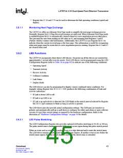
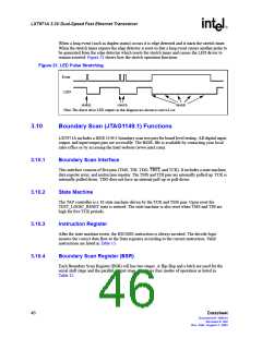
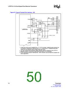
When a long event (such as duplex status) occurs it is edge detected and it starts the stretch timer.
When the stretch timer expires the edge detector is reset so that a long event causes another pulse to
be generated from the edge detector which resets the stretch timer and causes the LED driver to
remain asserted. Figure 21 shows how the stretch operation functions.
Figure 21. LED Pulse Stretching
Event
LED
stretch
stretch
stretch
Note: The direct drive LED outputs in this diagram are shown as activeLow.
3.10
Boundary Scan (JTAG1149.1) Functions
LXT971A includes a IEEE 1149.1 boundary scan test port for board level testing. All digital input,
output, and input/output pins are accessible. The BSDL file is available by contacting your local
sales office or by accessing the Intel website (www.intel.com).
3.10.1
3.10.2
3.10.3
3.10.4
Boundary Scan Interface
This interface consists of five pins (TMS, TDI, TDO, TRST, and TCK). It includes a state machine,
data register array, and instruction register. The TMS and TDI pins are internally pulled up. TCK is
internally pulled down. TDO does not have an internal pull-up or pull-down.
State Machine
The TAP controller is a 16 state machine driven by the TCK and TMS pins. Upon reset the
TEST_LOGIC_RESET state is entered. The state machine is also reset when TMS and TDI are
high for five TCK periods.
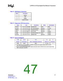
Instruction Register
After the state machine resets, the IDCODE instruction is always invoked. The decode logic
ensures the correct data flow to the Data registers according to the current instruction. Valid
instructions are listed in Table 13.
Boundary Scan Register (BSR)
Each Boundary Scan Register (BSR) cell has two stages. A flip-flop and a latch are used for the
serial shift stage and the parallel output stage. There are four modes of operation as listed in
Table 12.
46
Datasheet
Document #: 249414
Revision #: 002
Rev. Date: August 7, 2002

 INTEL [ INTEL ]