LXT971A 3.3V Dual-Speed Fast Ethernet Transceiver
4.3
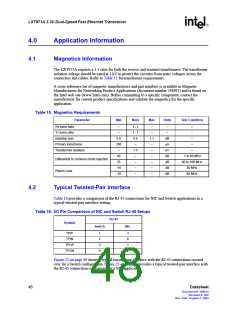
The Fiber Interface
The fiber interface consists of an LVPECL transmit and receive pair to an external fiber-optic
transceiver. Both 3.3 V fiber-optic transceivers and 5 V fiber-optic transceivers can be used with
the LXT971A.
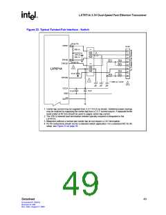
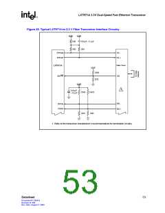
The following should occur in 3.3 V fiber transceiver applications as shown in Figure 25:
• The transmit pair should be DC-coupled with the 50 Ω/16 Ω pull-up combination
• The receive pair should be DC-coupled with an emitter current path for the fiber transceiver
• The signal detect pin should be DC-coupled with an emitter current path for the fiber
transceiver
Refer to the fiber transceiver manufacturer’s recommendations for termination circuitry. Figure 25
shows a typical example of an LXT971A-to-3.3 V fiber transceiver interface.
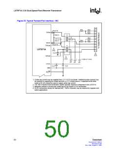
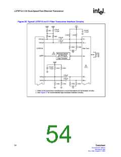
The following occurs in 5 V fiber transceiver applications as shown in Figure 26:
• The transmit pair should be AC-coupled and re-biased to 5 V PECL input levels
• The receive pair should be AC-coupled with an emitter current path for the fiber transceiver
and re-biased to 3.3 V LVPECL input levels.
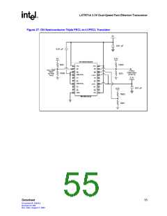
The signal detect pin on a 5 V fiber transceiver interface should use the logic translator circuitry as
shown in Figure 27. Refer to the fiber transceiver manufacturer’s recommendations for termination
circuitry. Figure 26 shows a typical example of an LXT971A-to-5 V fiber transceiver interface,
while Figure 27 shows the interface circuitry for the logic translator.
52
Datasheet
Document #: 249414
Revision #: 002
Rev. Date: August 7, 2002

 INTEL [ INTEL ]