LXT971A 3.3V Dual-Speed Fast Ethernet Transceiver
• Register bits 17.14 and 17.9 can be used to determine the link operating conditions (speed and
duplex).
3.9.1.1
3.9.2
Monitoring Next Page Exchange
The LXT971A offers an Alternate Next Page mode to simplify the next page exchange process.
Normally, Register bit 6.1 (Page Received) remains set until read. When Alternate Next Page mode
is enabled Register bit 6.1 is automatically cleared whenever a new negotiation process takes place.
This prevents the user from reading an old value in 6.1 and assuming that Registers 5 and 8
(Partner Ability) contain valid information. Additionally, the LXT971A uses Register bit 6.5 to
indicate when the current received page is the base page. This information is useful for recognizing
when next pages must be resent due to a new negotiation process starting. Register bits 6.1 and 6.5
are cleared when read.
LED Functions
The LXT971A incorporates three direct LED drivers. On power up all the drivers are asserted for
approximately 1 second after reset de-asserts. Each LED driver can be programmed using the LED
Configuration Register (refer to Table 56 on page 85) to indicate one of the following conditions:
• Operating Speed
• Transmit Activity
• Receive Activity
• Collision Condition
• Link Status
• Duplex Mode
The LED drivers can also be programmed to display various combined status conditions. For
example, setting Register bits 20.15:12 = 1101 produces the following combination of Link and
Activity indications:
• If Link is down LED is off.
• If Link is up LED is on.
• If Link is up and activity is detected, the LED blinks at the stretch interval selected by Register
bits 20.3:2 and continues to blink as long as activity is present.
The LED driver pins also provide initial configuration settings. The LED pins are sensitive to
polarity and automatically pull up or pull down to configure for either open drain or open collector
circuits (10 mA Max current rating) as required by the hardware configuration. Refer to the
discussion of “Hardware Configuration Settings” on page 30 for details.
3.9.2.1
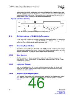
LED Pulse Stretching
The LED Configuration Register also provides optional LED pulse stretching to 30, 60, or 100 ms.
The pulse stretch time is further extended if the event occurs again during this pulse stretch period.
When an event such as receiving a packet occurs it is edge detected and it starts the stretch timer.
The LED driver remains asserted until the stretch timer expires. If another event occurs before the
stretch timer expires then the stretch timer is reset and the stretch time is extended.
Datasheet
45
Document #: 249414
Revision #: 002
Rev. Date: August 7, 2002

 INTEL [ INTEL ]