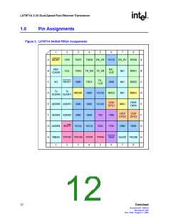
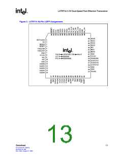
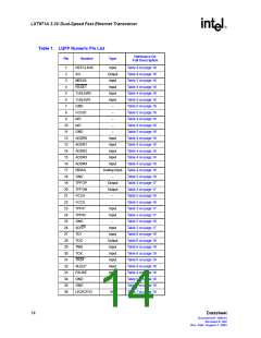
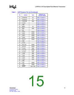
LXT971A 3.3V Dual-Speed Fast Ethernet Transceiver
2.0
Signal Descriptions
Note: Intel recommends that all inputs and multi-function pins be tied to the inactive states and all
outputs be left floating, if unused.
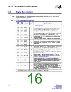
Table 2. LXT971A MII Signal Descriptions
PBGA LQFP
Symbol
Type1
Signal Description
Pin#
Pin#
Data Interface Pins
A3
B3
C4
A4
60
59
58
57
TXD3
Transmit Data. TXD is a bundle of parallel data signals that are
driven by the MAC. TXD<3:0> transitions synchronously with
respect to the TX_CLK. TXD<0> is the least significant bit.
TXD2
TXD1
TXD0
I
Transmit Enable. The MAC asserts this signal when it drives valid
B4
56
TX_EN
I
data on TXD. This signal must be synchronized to TX_CLK.
Transmit Clock. TX_CLK is sourced by the PHY in both 10 and
100 Mbps operations.
C5
55
TX_CLK
O
2.5 MHz for 10 Mbps operation, 25 MHz for 100 Mbps operation.
D6
C8
B8
A8
45
46
47
48
RXD3
RXD2
RXD1
RXD0
Receive Data. RXD is a bundle of parallel signals that transition
synchronously with respect to the RX_CLK. RXD<0> is the least
significant bit.
O
Receive Data Valid. The LXT971A asserts this signal when it drives
A7
A5
B5
49
53
54
RX_DV
RX_ER
TX_ER
O
O
I
valid data on RXD. This output is synchronous to RX_CLK.
Receive Error. Signals a receive error condition has occurred.
This output is synchronous to RX_CLK.
Transmit Error. Signals a transmit error condition. This signal must
be synchronized to TX_CLK.
Receive Clock. 25 MHz for 100 Mbps operation, 2.5 MHz for
10 Mbps operation. Refer to “Clock Requirements” on page 26 in
Section 3.0, “Functional Description”.
B6
B2
52
62
RX_CLK
COL
O
O
Collision Detected. The LXT971A asserts this output when a
collision is detected. This output remains High for the duration of the
collision. This signal is asynchronous and is inactive during full-
duplex operation.
Carrier Sense. During half-duplex operation (Register bit 0.8 = 0),
the LXT971A asserts this output when either transmitting or
receiving data packets. During full-duplex operation (Register bit 0.8
= 1), CRS is asserted only during receive. CRS assertion is
asynchronous with respect to RX_CLK. CRS is de-asserted on loss
of carrier, synchronous to RX_CLK.
A2
63
CRS
O
1. Type Column Coding: I = Input, O = Output, A = Analog, OD = Open Drain
16
Datasheet
Document #: 249414
Revision #: 002
Rev. Date: August 7, 2002

 INTEL [ INTEL ]