1-Gbit P30 Family
13.0
Security Modes
The device features security modes used to protect the information stored in the flash memory
array. The following sections describe each security mode in detail.
13.1
Block Locking
Individual instant block locking is used to protect user code and/or data within the flash memory
array. All blocks power up in a locked state to protect array data from being altered during power
transitions. Any block can be locked or unlocked with no latency. Locked blocks cannot be
programmed or erased; they can only be read.
Software-controlled security is implemented using the Block Lock and Block Unlock commands.
Hardware-controlled security can be implemented using the Block Lock-Down command along
with asserting WP#. Also, VPP data security can be used to inhibit program and erase operations
(see Section 11.6, “Program Protection” on page 66 and Section 12.4, “Erase Protection” on
page 68).
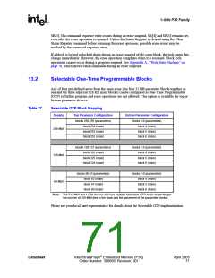
The P30 device also offers four pre-defined areas in the main array that can be configured as One-
Time Programmable (OTP) for the highest level of security. These include the four 32 KB
parameter blocks together as one and the three adjacent 128 KB main blocks. This is available for
top or bottom parameter devices.
13.1.1
Lock Block
To lock a block, issue the Lock Block Setup command. The next command must be the Lock Block
command issued to the desired block’s address (see Section 9.2, “Device Commands” on page 50
and Figure 46, “Block Lock Operations Flowchart” on page 91). If the Set Read Configuration
Register command is issued after the Block Lock Setup command, the device configures the RCR
instead.
Block lock and unlock operations are not affected by the voltage level on VPP. The block lock bits
may be modified and/or read even if VPP is at or below VPPLK
.
13.1.2
13.1.3
Unlock Block
The Unlock Block command is used to unlock blocks (see Section 9.2, “Device Commands” on
page 50). Unlocked blocks can be read, programmed, and erased. Unlocked blocks return to a
locked state when the device is reset or powered down. If a block is in a lock-down state, WP#
must be deasserted before it can be unlocked (see Figure 32, “Block Locking State Diagram” on
page 70).
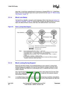
Lock-Down Block
A locked or unlocked block can be locked-down by writing the Lock-Down Block command
sequence (see Section 9.2, “Device Commands” on page 50). Blocks in a lock-down state cannot
be programmed or erased; they can only be read. However, unlike locked blocks, their locked state
cannot be changed by software commands alone. A locked-down block can only be unlocked by
issuing the Unlock Block command with WP# deasserted. To return an unlocked block to locked-
Datasheet
Intel StrataFlash® Embedded Memory (P30)
Order Number: 306666, Revision: 001
April 2005
69

 INTEL [ INTEL ]