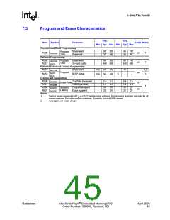
1-Gbit P30 Family
9.1.2
Writes
To perform a write operation, both CE# and WE# are asserted while RST# and OE# are deasserted.
During a write operation, address and data are latched on the rising edge of WE# or CE#,
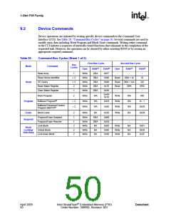
whichever occurs first. Table 20, “Command Bus Cycles” on page 50 shows the bus cycle
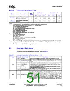
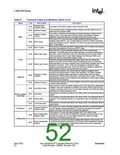
sequence for each of the supported device commands, while Table 21, “Command Codes and
Definitions” on page 51 describes each command. See Section 7.0, “AC Characteristics” on
page 33 for signal-timing details.
Note:
Write operations with invalid VCC and/or VPP voltages can produce spurious results and should not
be attempted.
9.1.3
Output Disable
When OE# is deasserted, device outputs DQ[15:0] are disabled and placed in a high-impedance
(High-Z) state, WAIT is also placed in High-Z.
9.1.4
Standby
When CE# is deasserted the device is deselected and placed in standby, substantially reducing
power consumption. In standby, the data outputs are placed in High-Z, independent of the level
placed on OE#. Standby current, ICCS, is the average current measured over any 5 ms time interval,
5 µs after CE# is deasserted. During standby, average current is measured over the same time
interval 5 µs after CE# is deasserted.
When the device is deselected (while CE# is deasserted) during a program or erase operation, it
continues to consume active power until the program or erase operation is completed.
9.1.5
Reset
As with any automated device, it is important to assert RST# when the system is reset. When the
system comes out of reset, the system processor attempts to read from the flash memory if it is the
system boot device. If a CPU reset occurs with no flash memory reset, improper CPU initialization
may occur because the flash memory may be providing status information rather than array data.
Flash memory devices from Intel allow proper CPU initialization following a system reset through
the use of the RST# input. RST# should be controlled by the same low-true reset signal that resets
the system CPU.
After initial power-up or reset, the device defaults to asynchronous Read Array, and the Status
Register is set to 0x80. Asserting RST# de-energizes all internal circuits, and places the output
drivers in High-Z. When RST# is asserted, the device shuts down the operation in progress, a
process which takes a minimum amount of time to complete. When RST# has been deasserted, the
device is reset to asynchronous Read Array state.
Note:
If RST# is asserted during a program or erase operation, the operation is terminated and the
memory contents at the aborted location (for a program) or block (for an erase) are no longer valid,
because the data may have been only partially written or erased.
When returning from a reset (RST# deasserted), a minimum wait is required before the initial read
access outputs valid data. Also, a minimum delay is required after a reset before a write cycle can
be initiated. After this wake-up interval passes, normal operation is restored. See Section 7.0, “AC
Characteristics” on page 33 for details about signal-timing.
Datasheet
Intel StrataFlash® Embedded Memory (P30)
Order Number: 306666, Revision: 001
April 2005
49

 INTEL [ INTEL ]