DC & Switching Characteristics
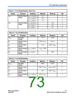
Table 5–2. MAX II Device Recommended Operating Conditions (Part 2 of 2)
Symbol
Parameter
Conditions
Minimum
Maximum
Unit
TJ
Operating
junction
temperature
Commercial range
Industrial range
0
85
° C
° C
° C
–40
–40
100
125
Extended range (5)
Notes to Table 5–2:
(1) MAX II device in-system programming and/or UFM programming via JTAG or logic array is not guaranteed outside
the recommended operating conditions (i.e., if brown-out occurs in the system during a potential write/program
sequence to the UFM, users are recommended to read back UFM contents and verify against the intended write data).
(2) Minimum DC input is –0.5 V. During transitions, the inputs may undershoot to –2.0 V for input currents less than 100
mA and periods shorter than 20 ns.
(3) During transitions, the inputs may overshoot to the voltages shown in the following table based upon input duty
cycle. The DC case is equivalent to 100% duty cycle. For more information on 5.0-V tolerance refer to the chapter on
Using MAX II Devices in Multi-Voltage Systems.
VIN
Max. Duty Cycle
4.0 V 100% (DC)
4.1
4.2
4.3
4.4
4.5
90%
50%
30%
17%
10%
(4) All pins, including clock, I/O, and JTAG pins, may be driven before VCCINT and VCCIO are powered.
(5) For the extended temperature range of 100 to 125º C, MAX II UFM programming (erase/write) is only supported via
the JTAG interface. UFM programming via the logic array interface is not guaranteed in this range.
Programming/Erasure Specifications
Table 5–3 shows the MAX II device family programming/erasure
specifications.
Table 5–3. MAX II Device Programming/Erasure Specifications
Parameter
Minimum
Typical
Maximum
Unit
Erase and reprogram cycles
Cycles
100 (1)
Note to Table 5–3:
(1) This specification applies to the user flash memory (UFM) and CFM blocks.
Altera Corporation
July 2006
Core Version a.b.c variable
5–3
MAX II Device Handbook, Volume 1

 INTEL [ INTEL ]