1–4
Chapter 1: Cyclone IV Device Datasheet
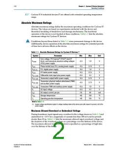
Operating Conditions
Recommended Operating Conditions
This section lists the functional operation limits for AC and DC parameters for
Cyclone IV devices. Table 1–3 and Table 1–4 list the steady-state voltage and current
values expected from Cyclone IV E and Cyclone IV GX devices. All supplies must be
strictly monotonic without plateaus.
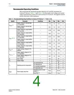
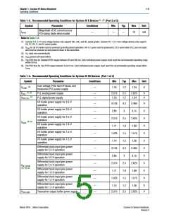
Table 1–3. Recommended Operating Conditions for Cyclone IV E Devices (1), (2) (Part 1 of 2)
Symbol
Parameter
Conditions
Min
Typ
Max
Unit
Supply voltage for internal logic,
1.2-V operation
—
1.15
1.2
1.25
V
(3)
VCCINT
Supply voltage for internal logic,
1.0-V operation
—
—
—
—
—
—
—
—
—
—
0.97
3.135
2.85
1.0
3.3
3
1.03
3.465
3.15
V
V
V
V
V
V
V
V
V
V
Supply voltage for output buffers,
3.3-V operation
Supply voltage for output buffers,
3.0-V operation
Supply voltage for output buffers,
2.5-V operation
2.375
1.71
2.5
1.8
1.5
1.2
2.5
1.2
1.0
2.625
1.89
(3), (4)
VCCIO
Supply voltage for output buffers,
1.8-V operation
Supply voltage for output buffers,
1.5-V operation
1.425
1.14
1.575
1.26
Supply voltage for output buffers,
1.2-V operation
Supply (analog) voltage for PLL
regulator
(3)
VCCA
2.375
1.15
2.625
1.25
Supply (digital) voltage for PLL,
1.2-V operation
(3)
VCCD_PLL
Supply (digital) voltage for PLL,
1.0-V operation
0.97
1.03
VI
Input voltage
—
–0.5
0
—
—
—
—
—
—
3.6
VCCIO
85
V
VO
Output voltage
—
V
For commercial use
For industrial use
For extended temperature
For automotive use
Standard power-on reset
0
°C
°C
°C
°C
–40
–40
–40
100
125
125
TJ
Operating junction temperature
Power supply ramp time
50 µs
50 µs
—
—
50 ms
3 ms
—
—
(5)
(POR)
tRAMP
(6)
Fast POR
Cyclone IV Device Handbook,
Volume 3
March 2016 Altera Corporation

 INTEL [ INTEL ]