1–2
Chapter 1: Cyclone IV Device Datasheet
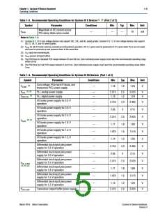
Operating Conditions
1
Cyclone IV E industrial devices I7 are offered with extended operating temperature
range.
Absolute Maximum Ratings
Absolute maximum ratings define the maximum operating conditions for Cyclone IV
devices. The values are based on experiments conducted with the device and
theoretical modeling of breakdown and damage mechanisms. The functional
operation of the device is not implied at these conditions. Table 1–1 lists the absolute
maximum ratings for Cyclone IV devices.
c
Conditions beyond those listed in Table 1–1 cause permanent damage to the device.
Additionally, device operation at the absolute maximum ratings for extended periods
of time have adverse effects on the device.
Table 1–1. Absolute Maximum Ratings for Cyclone IV Devices (1)
Symbol
VCCINT
VCCA
Parameter
Min
Max
Unit
Core voltage, PCI Express (PCIe) hard IP
block, and transceiver physical coding sublayer
(PCS) power supply
–0.5
1.8
V
Phase-locked loop (PLL) analog power supply
–0.5
–0.5
–0.5
–0.5
–0.5
3.75
1.8
V
V
V
V
V
VCCD_PLL PLL digital power supply
VCCIO I/O banks power supply
3.75
4.5
VCC_CLKIN Differential clock input pins power supply
VCCH_GXB Transceiver output buffer power supply
3.75
Transceiver physical medium attachment (PMA)
and auxiliary power supply
VCCA_GXB
–0.5
3.75
V
VCCL_GXB Transceiver PMA and auxiliary power supply
–0.5
–0.5
–25
–65
–40
1.8
4.2
40
V
V
VI
DC input voltage
IOUT
TSTG
TJ
DC output current, per pin
Storage temperature
mA
°C
°C
150
125
Operating junction temperature
Note to Table 1–1:
(1) Supply voltage specifications apply to voltage readings taken at the device pins with respect to ground, not at the
power supply.
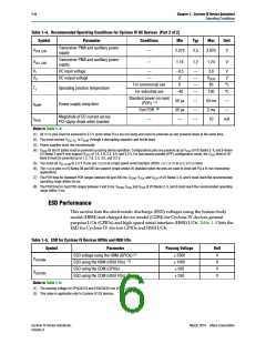
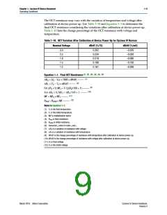
Maximum Allowed Overshoot or Undershoot Voltage
During transitions, input signals may overshoot to the voltage shown in Table 1–2 and
undershoot to –2.0 V for a magnitude of currents less than 100 mA and for periods
shorter than 20 ns. Table 1–2 lists the maximum allowed input overshoot voltage and
the duration of the overshoot voltage as a percentage over the lifetime of the device.
The maximum allowed overshoot duration is specified as a percentage of high-time
over the lifetime of the device.
Cyclone IV Device Handbook,
Volume 3
March 2016 Altera Corporation

 INTEL [ INTEL ]