1–12
Chapter 1: Cyclone IV Device Datasheet
Operating Conditions
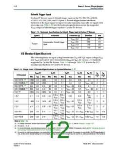
Schmitt Trigger Input
Cyclone IV devices support Schmitt trigger input on the TDI
, TMS, TCK, nSTATUS,
nCONFIG, nCE,
CONF_DONE, and DCLK pins. A Schmitt trigger feature introduces
hysteresis to the input signal for improved noise immunity, especially for signals with
slow edge rate. Table 1–14 lists the hysteresis specifications across the supported
V
CCIO range for Schmitt trigger inputs in Cyclone IV devices.
Table 1–14. Hysteresis Specifications for Schmitt Trigger Input in Cyclone IV Devices
Symbol
Parameter
Conditions (V)
Minimum
200
Unit
mV
mV
mV
mV
V
V
CCIO = 3.3
CCIO = 2.5
200
Hysteresis for Schmitt trigger
input
VSCHMITT
VCCIO = 1.8
CCIO = 1.5
140
V
110
I/O Standard Specifications
The following tables list input voltage sensitivities (VIH and VIL), output voltage (VOH
and VOL), and current drive characteristics (IOH and IOL), for various I/O standards
supported by Cyclone IV devices. Table 1–15 through Table 1–20 provide the I/O
standard specifications for Cyclone IV devices.
(2)
Table 1–15. Single-Ended I/O Standard Specifications for Cyclone IV Devices (1),
VCCIO (V)
Typ
VIL (V)
VIH (V)
Max
VOL (V)
Max
VOH (V)
Min
IOL
IOH
I/O Standard
(mA)
(mA)
(4)
(4)
Min
Max
Min
Max
Min
(3)
3.3-V LVTTL
3.135
3.135
2.85
3.3
3.3
3.0
3.0
2.5
3.465
3.465
—
—
0.8
0.8
0.8
0.8
0.7
1.7
1.7
1.7
1.7
1.7
3.6
0.45
0.2
2.4
VCCIO – 0.2
2.4
4
2
–4
–2
(3)
(3)
3.3-V LVCMOS
3.6
(3)
3.0-V LVTTL
3.15 –0.3
3.15 –0.3
2.625 –0.3
VCCIO + 0.3
VCCIO + 0.3
VCCIO + 0.3
0.45
0.2
4
–4
3.0-V LVCMOS
2.85
VCCIO – 0.2
2.0
0.1
1
–0.1
–1
(3)
2.5 V
2.375
0.4
0.35 x 0.65 x
VCCIO VCCIO
VCCIO
0.45
–
1.8 V
1.71
1.425
1.14
2.85
2.85
1.8
1.5
1.2
3.0
3.0
1.89 –0.3
1.575 –0.3
1.26 –0.3
2.25
0.45
2
2
–2
–2
0.35 x 0.65 x
VCCIO VCCIO
0.25 x
VCCIO
0.75 x
VCCIO
1.5 V
VCCIO + 0.3
VCCIO + 0.3
0.35 x 0.65 x
0.25 x
VCCIO
0.75 x
VCCIO
1.2 V
2
–2
VCCIO
VCCIO
0.3 x
VCCIO
0.5 x
VCCIO
3.0-V PCI
3.0-V PCI-X
3.15
3.15
—
—
VCCIO + 0.3 0.1 x VCCIO 0.9 x VCCIO
VCCIO + 0.3 0.1 x VCCIO 0.9 x VCCIO
1.5
1.5
–0.5
–0.5
0.35 x
VCCIO
0.5 x
VCCIO
Notes to Table 1–15:
(1) For voltage-referenced receiver input waveform and explanation of terms used in Table 1–15, refer to “Glossary” on page 1–37.
(2) AC load CL = 10 pF
(3) For more information about interfacing Cyclone IV devices with 3.3/3.0/2.5-V LVTTL/LVCMOS I/O standards, refer to AN 447: Interfacing Cyclone III
and Cyclone IV Devices with 3.3/3.0/2.5-V LVTTL/LVCMOS I/O Systems.
(4) To meet the IOL and IOH specifications, you must set the current strength settings accordingly. For example, to meet the 3.3-V LVTTL specification (4
mA), set the current strength settings to 4 mA or higher. Setting at lower current strength may not meet the IOL and IOH specifications in the handbook.
Cyclone IV Device Handbook,
Volume 3
March 2016 Altera Corporation

 INTEL [ INTEL ]