Processor Configuration Registers
2.6.39
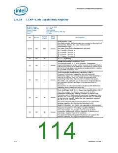
LCTL—Link Control Register
This register allows control of PCI Express* link.
B/D/F/Type:
Address Offset:
Reset Value:
Access:
0/1/0–2/PCI
B0–B1h
0000h
RW, RO, RW-V
16 bits
Size:
BIOS Optimal Default
00h
Reset
Value
RST/
PWR
Bit
Access
Description
15:12
RO
0h
Reserved (RSVD)
Link Autonomous Bandwidth Interrupt Enable (LABIE)
When set, this bit enables the generation of an interrupt to
indicate that the Link Autonomous Bandwidth Status bit has been
set.
This bit is not applicable and is reserved for Endpoint devices, PCI
Express to PCI/PCI-X bridges, and Upstream Ports of Switches.
11
RW
0b
Uncore
Devices that do not implement the Link Bandwidth Notification
capability must hardwire this bit to 0b.
Link Bandwidth Management Interrupt Enable (LBMIE)
When set, this bit enables the generation of an interrupt to
indicate that the Link Bandwidth Management Status bit has
been set.
This bit is not applicable and is reserved for Endpoint devices, PCI
Express to PCI/PCI-X bridges, and Upstream Ports of Switches.
10
RW
RW
0b
0b
Uncore
Uncore
Hardware Autonomous Width Disable (HAWD)
When set, this bit disables hardware from changing the Link
width for reasons other than attempting to correct unreliable Link
operation by reducing Link width
9
Devices that do not implement the ability autonomously to
change Link width are permitted to hardwire this bit to 0b.
Enable Clock Power Management (ECPM)
Applicable only for form factors that support a "Clock Request"
(CLKREQ#) mechanism, this enable functions as follows
0 = Clock power management is disabled and device must hold
CLKREQ# signal low
1 = When this bit is set to 1 the device is permitted to use
CLKREQ# signal to power manage link clock according to
protocol defined in appropriate form factor specification.
8
RO
0b
Uncore
Reset Value of this field is 0b.
Components that do not support Clock Power Management (as
indicated by a 0b value in the Clock Power Management bit of the
Link Capabilities Register) must hardwire this bit to 0b.
Extended Synch (ES)
0 = Standard Fast Training Sequence (FTS).
1 = Forces the transmission of additional ordered sets when
exiting the L0s state and when in the Recovery state.
This mode provides external devices (such as, logic analyzers)
monitoring the Link time to achieve bit and symbol lock before
the link enters L0 and resumes communication.
7
RW
0b
Uncore
This is a test mode only and may cause other undesired side
effects such as buffer overflows or underruns.
116
Datasheet, Volume 2

 INTEL [ INTEL ]