Register and Memory Mapping
2.
3.
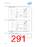
The ICH10 can optionally configure the USB ports from a 6-6 configuration into a 8-4
configuration, with 8 ports on D29:F7 EHCI and 4 ports on D26:F7 EHCI. In the 8-4
configuration UHCI #6 will be mapped to D29:F3. In the 6-6 configuration UHCI #6 will be
mapped to D26:F2.
SATA controller 2 (D31:F5) is only visible in ICH10 desktop components and when D31:F2
CC.SCC=01h.
9.2
PCI Configuration Map
Each PCI function on the ICH10 has a set of PCI configuration registers. The register
address map tables for these register sets are included at the beginning of the chapter
for the particular function.
Configuration Space registers are accessed through configuration cycles on the PCI bus
by the Host bridge using configuration mechanism #1 detailed in the PCI Local Bus
Specification, Revision 2.3.
Some of the PCI registers contain reserved bits. Software must deal correctly with
fields that are reserved. On reads, software must use appropriate masks to extract the
defined bits and not rely on reserved bits being any particular value. On writes,
software must ensure that the values of reserved bit positions are preserved. That is,
the values of reserved bit positions must first be read, merged with the new values for
other bit positions and then written back. Note the software does not need to perform
read, merge, write operation for the configuration address register.
In addition to reserved bits within a register, the configuration space contains reserved
locations. Software should not write to reserved PCI configuration locations in the
device-specific region (above address offset 3Fh).
9.3
I/O Map
The I/O map is divided into Fixed and Variable address ranges. Fixed ranges cannot be
moved, but in some cases can be disabled. Variable ranges can be moved and can also
be disabled.
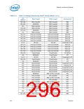
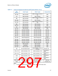
9.3.1
Fixed I/O Address Ranges
Table 9-2 shows the Fixed I/O decode ranges from the processor perspective. Note that
for each I/O range, there may be separate behavior for reads and writes. DMI (Direct
Media Interface) cycles that go to target ranges that are marked as “Reserved” will not
be decoded by the ICH10, and will be passed to PCI unless the Subtractive Decode
Policy bit is set (D31:F0:Offset 42h, bit 0). If a PCI master targets one of the fixed I/O
target ranges, it will be positively decoded by the ICH10 in medium speed.
Address ranges that are not listed or marked “Reserved” are not decoded by the ICH10
(unless assigned to one of the variable ranges).
Datasheet
295

 INTEL [ INTEL ]