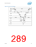
Register and Memory Mapping
9
Register and Memory Mapping
The ICH10 contains registers that are located in the processor’s I/O space and memory
space and sets of PCI configuration registers that are located in PCI configuration
space. This chapter describes the ICH10 I/O and memory maps at the register-set
level. Register access is also described. Register-level address maps and Individual
register bit descriptions are provided in the following chapters. The following notations
and definitions are used in the register/instruction description chapters.
RO
Read Only. In some cases, if a register is read only, writes to this
register location have no effect. However, in other cases, two
separate registers are located at the same location where a read
accesses one of the registers and a write accesses the other
register. See the I/O and memory map tables for details.
WO
Write Only. In some cases, if a register is write only, reads to this
register location have no effect. However, in other cases, two
separate registers are located at the same location where a read
accesses one of the registers and a write accesses the other
register. See the I/O and memory map tables for details.
R/W
Read/Write. A register with this attribute can be read and
written.
R/WC
Read/Write Clear. A register bit with this attribute can be read
and written. However, a write of 1 clears (sets to 0) the
corresponding bit and a write of 0 has no effect.
R/WO
Read/Write-Once. A register bit with this attribute can be
written only once after power up. After the first write, the bit
becomes read only.
R/WLO
Read/Write, Lock-Once. A register bit with this attribute can be
written to the non-locked value multiple times, but to the locked
value only once. After the locked value has been written, the bit
becomes read only.
Reserved
Default
The value of reserved bits must never be changed. For details
see Section 9.2.
When ICH10 is reset, it sets its registers to predetermined
default states. The default state represents the minimum
functionality feature set required to successfully bring up the
system. Hence, it does not represent the optimal system
configuration. It is the responsibility of the system initialization
software to determine configuration, operating parameters, and
optional system features that are applicable, and to program the
ICH10 registers accordingly.
Bold
Register bits that are highlighted in bold text indicate that the
bit is implemented in the ICH10. Register bits that are not
implemented or are hardwired will remain in plain text.
Datasheet
293

 INTEL [ INTEL ]