Functional Description
5.9.4.1
5.9.4.2
Edge-Triggered Operation
In this case, the “Assert Message” is sent when there is an inactive-to-active edge on
the interrupt.
Level-Triggered Operation
In this case, the “Assert Message” is sent when there is an inactive-to-active edge on
the interrupt. If after the EOI the interrupt is still active, then another “Assert Message”
is sent to indicate that the interrupt is still active.
5.9.4.3
5.9.4.4
Registers Associated with Front Side Bus Interrupt Delivery
Capabilities Indication: The capability to support Front Side Bus interrupt delivery is
indicated via ACPI configuration techniques. This involves the BIOS creating a data
structure that gets reported to the ACPI configuration software.
Interrupt Message Format
The ICH10 writes the message to PCI (and to the Host controller) as a 32-bit memory
write cycle. It uses the formats shown in Table 5-17 and Table 5-18 for the address and
data.
The local APIC (in the processor) has a delivery mode option to interpret Front Side Bus
messages as a SMI in which case the processor treats the incoming interrupt as a SMI
instead of as an interrupt. This does not mean that the ICH10 has any way to have a
SMI source from ICH10 power management logic cause the I/O APIC to send an SMI
message (there is no way to do this). The ICH10’s I/O APIC can only send interrupts
due to interrupts which do not include SMI, NMI or INIT. This means that in IA-32/
Intel® 64 based platforms, Front Side Bus interrupt message format delivery modes
010 (SMI/PMI), 100 (NMI), and 101 (INIT) as indicated in this section, must not be
used and is not supported. Only the hardware pin connection is supported by ICH10.
:
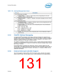
Table 5-17. Interrupt Message Address Format
Bit
Description
31:20
19:12
Will always be FEEh
Destination ID: This is the same as bits 63:56 of the I/O Redirection Table entry for
the interrupt associated with this message.
Extended Destination ID: This is the same as bits 55:48 of the I/O Redirection
Table entry for the interrupt associated with this message.
11:4
Redirection Hint: This bit is used by the processor host bridge to allow the interrupt
message to be redirected.
0 = The message will be delivered to the agent (processor) listed in bits 19:12.
1 = The message will be delivered to an agent with a lower interrupt priority This can
be derived from bits 10:8 in the Data Field (see below).
3
The Redirection Hint bit will be a 1 if bits 10:8 in the delivery mode field associated
with corresponding interrupt are encoded as 001 (Lowest Priority). Otherwise, the
Redirection Hint bit will be 0
Destination Mode: This bit is used only the Redirection Hint bit is set to 1. If the
Redirection Hint bit and the Destination Mode bit are both set to 1, then the logical
destination mode is used, and the redirection is limited only to those processors that
are part of the logical group as based on the logical ID.
2
1:0
Will always be 00.
130
Datasheet

 INTEL [ INTEL ]