Functional Description
5.9
Advanced Programmable Interrupt Controller
(APIC) (D31:F0)
In addition to the standard ISA-compatible PIC described in the previous chapter, the
ICH10 incorporates the APIC. While the standard interrupt controller is intended for use
in a uni-processor system, APIC can be used in either a uni-processor or multi-
processor system.
5.9.1
Interrupt Handling
The I/O APIC handles interrupts very differently than the 8259. Briefly, these
differences are:
• Method of Interrupt Transmission. The I/O APIC transmits interrupts through
memory writes on the normal datapath to the processor, and interrupts are handled
without the need for the processor to run an interrupt acknowledge cycle.
• Interrupt Priority. The priority of interrupts in the I/O APIC is independent of the
interrupt number. For example, interrupt 10 can be given a higher priority than
interrupt 3.
• More Interrupts. The I/O APIC in the ICH10 supports a total of 24 interrupts.
• Multiple Interrupt Controllers. The I/O APIC architecture allows for multiple I/O
APIC devices in the system with their own interrupt vectors.
5.9.2
Interrupt Mapping
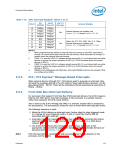
The I/O APIC within the ICH10 supports 24 APIC interrupts. Each interrupt has its own
unique vector assigned by software. The interrupt vectors are mapped as follows, and
match “Config 6” of the Multi-Processor Specification.
Table 5-16. APIC Interrupt Mapping1 (Sheet 1 of 2)
Via
SERIRQ
Direct
from Pin
Via PCI
Message
IRQ #
Internal Modules
Cascade from 8259 #1
0
1
No
Yes
No
No
No
No
No
No
No
No
No
No
No
No
No
No
No
No
No
No
Yes
No
2
8254 Counter 0, HPET #0 (legacy mode)
3
Yes
Yes
Yes
Yes
Yes
No
Yes
Yes
Yes
Yes
Yes
No
4
5
6
7
8
RTC, HPET #1 (legacy mode)
Option for SCI, TCO
9
Yes
Yes
Yes
Yes
No
Yes
Yes
Yes
Yes
No
10
11
12
13
14
15
Option for SCI, TCO
HPET #2, Option for SCI, TCO (Note2)
HPET #3 (Note 3)
FERR# logic
Yes
Yes
Yes
Yes
SATA Primary (legacy mode)
SATA Secondary (legacy mode)
128
Datasheet

 INTEL [ INTEL ]