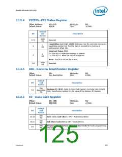
Intel® HD Audio (D27:F0)
10.1.1.3
10.1.1.4
Relationship between HDA_DOCKRST# and HDA_RST#
HDA_RST# is asserted when RESET# occurs or when the CRST# bit is 0. In both of
these cases GCTL.DA and GSTS.DM bits are cleared, HDA_DOCK_EN# is deasserted,
and HDA_DOCKRST# is asserted. After reset, software is responsible for initiating the
electrical connection, discovery, and enumeration process just as it would for a normal
docking event.
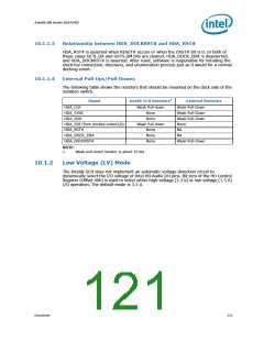
External Pull-Ups/Pull-Downs
The following table shows the resistors that should be mounted on the dock side of the
isolation switch.
Signal
Intel® SCH Resistors1
External Resistors
Weak Pull-Down
HDA_CLK
HDA_SYNC
HDA_SDO
Weak Pull-down
None
Weak Pull-Down
Weak Pull-Down
None
None
HDA_SDI (from docked codec(s))s
HDA_RST#
Weak Pull-down
None
NA
HDA_DOCK_EN#
None
NA
HDA_DOCKRST#
None
Weak Pull-Down
NOTE:
1.
Weak pull-down resistor is about 10 kΩ.
10.1.2
Low Voltage (LV) Mode
The Intel® SCH does not implement an automatic voltage detection circuit to
dynamically select the I/O voltage of Intel HD Audio I/O pins. Bit zero of the HD Control
Register (Offset 40h) is used to select either high-voltage (3.3 V) or low-voltage (1.5 V)
I/O operation. The default mode is 3.3 V.
Datasheet
121

 INTEL [ INTEL ]