Electrical Specifications
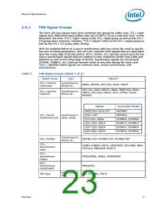
2.6.2
GTL+ Asynchronous Signals
Legacy input signals such as A20M#, IGNNE#, INIT#, SMI#, and STPCLK# use CMOS
input buffers. All of these signals follow the same DC requirements as GTL+ signals;
however, the outputs are not actively driven high (during a logical 0 to 1 transition) by
the processor. These signals do not have setup or hold time specifications in relation to
BCLK[1:0].
All of the GTL+ Asynchronous signals are required to be asserted/de-asserted for at
least six BCLKs in order for the processor to recognize the proper signal state. See
Section 2.6.3 for the DC specifications for the GTL+ Asynchronous signal groups. See
Section 6.2 for additional timing requirements for entering and leaving the low power
states.
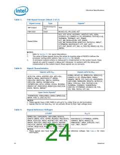
2.6.3
Processor DC Specifications
The processor DC specifications in this section are defined at the processor core (pads)
unless otherwise stated. All specifications apply to all frequencies and cache sizes
unless otherwise stated.
Table 10.
GTL+ Signal Group DC Specifications
Symbol
Parameter
Min
Max
Unit Notes1
2, 3
VIL
VIH
VOH
Input Low Voltage
Input High Voltage
Output High Voltage
0.0
GTLREF – (0.10 * VTT)
V
4, 5, 3
GTLREF + (0.10 * VTT)
0.90*VTT
VTT
VTT
V
3, 5
V
VTT_MAX
[(0.50*RTT_MIN)+(RON_MIN)]
/
IOL
ILI
Output Low Current
N/A
N/A
A
-
Input Leakage
Current
6
± 200
µA
Output Leakage
Current
7
ILO
N/A
6
± 200
12
µA
RON
Buffer On Resistance
Ω
NOTES:
1. Unless otherwise noted, all specifications in this table apply to all processor frequencies.
2. VIL is defined as the voltage range at a receiving agent that will be interpreted as a logical low value.
3. The VTT referred to in these specifications is the instantaneous VTT.
4. VIH is defined as the voltage range at a receiving agent that will be interpreted as a logical high value.
5. VIH and VOH may experience excursions above VTT. However, input signal drivers must comply with the
signal quality specifications.
6. Leakage to VSS with land held at VTT.
7. Leakage to VTT with land held at 300 mV.
Datasheet
25

 INTEL [ INTEL ]