Electrical Specifications
Figure 1.
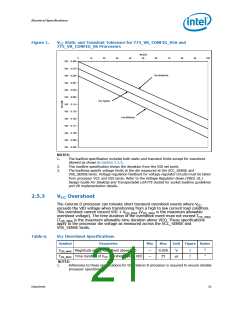
V
CC Static and Transient Tolerance for 775_VR_CONFIG_05A and
775_VR_CONFIG_06 Processors
Icc [A]
0
10
20
30
40
50
60
70
80
90
100
VID - 0.000
VID - 0.019
VID - 0.038
VID - 0.057
VID - 0.076
VID - 0.095
VID - 0.114
VID - 0.133
VID - 0.152
VID - 0.171
VID - 0.190
VID - 0.209
VID - 0.228
Vcc Maximum
Vcc Typical
Vcc Minimum
NOTES:
1.
The loadline specification includes both static and transient limits except for overshoot
allowed as shown in Section 2.5.3.
2.
3.
This loadline specification shows the deviation from the VID set point.
The loadlines specify voltage limits at the die measured at the VCC_SENSE and
VSS_SENSE lands. Voltage regulation feedback for voltage regulator circuits must be taken
from processor VCC and VSS lands. Refer to the Voltage Regulator-Down (VRD) 10.1
Design Guide For Desktop and Transportable LGA775 Socket for socket loadline guidelines
and VR implementation details.
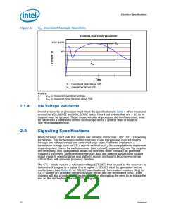
2.5.3
V
Overshoot
CC
The Celeron D processor can tolerate short transient overshoot events where VCC
exceeds the VID voltage when transitioning from a high to low current load condition.
This overshoot cannot exceed VID + VOS_MAX (VOS_MAX is the maximum allowable
overshoot voltage). The time duration of the overshoot event must not exceed TOS_MAX
(TOS_MAX is the maximum allowable time duration above VID). These specifications
apply to the processor die voltage as measured across the VCC_SENSE and
VSS_SENSE lands.
Table 6.
Vcc Overshoot Specifications
Symbol
Parameter
Min
Max
Unit Figure Notes
1
VOS_MAX Magnitude of VCC overshoot above VID
TOS_MAX Time duration of VCC overshoot above VID
NOTES:
—
—
0.050
25
V
2
2
1
μs
1.
Adherence to these specifications for the Celeron D processor is required to ensure reliable
processor operation.
Datasheet
21

 INTEL [ INTEL ]