Ultra-Low Voltage Intel® Celeron® Processor — 650 MHz and 400 MHz
8.1.58
8.1.59
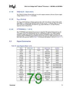
VID[4:0] (O – Open-drain)
The VID[4:0] (Voltage ID) pins/balls may be used to support automatic selection of power supply
voltages. Refer to Section 3.2.4 for details.
V
(Analog)
REF
The VREF (AGTL Reference Voltage) signal provides a DC level reference voltage for the AGTL
input buffers. A voltage divider should be used to divide VCCT by 2/3. Resistor values of 1.00 kΩ
and 2.00 kΩ are recommended. Decouple the VREF signal with three 0.1-µF high-frequency
capacitors close to the processor.
8.1.60
VTTPWRGD (I – 1.25 V)
The VTTPWRGD signal informs the processor to output the VID signals. During power up, the
VID signals will be in an indeterminate state for a small period of time. The voltage regulator
should not sample and/or latch the VID signals until the VTTPWRGD signal is asserted. The
assertion of the VTTPWRGD signal indicates that the VID signals are stable and are driven to the
final state by the processor. Refer to Figure 12 for the power up sequence. (Also see Section 4.3.1.)
8.2
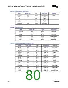
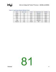
Signal Summaries
Table 45. Input Signals (Sheet 1 of 2)
Name
A20M#
Active Level
Low
Clock
Signal Group
Qualified
Asynch
—
CMOS
System Bus
System Bus
System Bus
System Bus
CMOS
Always
Always
BCLK
BCLK#
BPRI#
High
Low
Low
Low
Low
Low
Low
High
High
High
High
High
Low
High
Low
Low
Low
—
Always
BCLK
BCLK
Asynch
Asynch
Asynch
Asynch
Asynch
Asynch
Asynch
—
Always
DEFER#
FLUSH#
IGNNE#
INIT#
Always
Always
CMOS
Always
System Bus
CMOS
Always
INTR
APIC disabled mode
APIC enabled mode
APIC disabled mode
LINT[1:0]
NMI
APIC
CMOS
NCTRL
PICCLK
PREQ#
PWRGOOD
RESET#
RSP#
APIC
Always
Always
Always
Always
Always
Always
Asynch
Asynch
BCLK
BCLK
Asynch
Implementation
Implementation
System Bus
System Bus
CMOS
SMI#
Datasheet
79

 INTEL [ INTEL ]