Ultra-Low Voltage Intel® Celeron® Processor — 650 MHz and 400 MHz
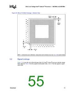
Figure 24. Micro FC-BGA Package – Bottom View
1.625 (S)
4 places
AF
AD
AB
Y
AE
AC
AA
W
U
1.625 (S)
4 places
V
T
R
P
N
M
K
L
J
H
G
F
E
D
C
B
A
1
3
13 15 17
11
10 12 14 16 18
5
7
9
19 21 23 25
25X 1.27
(e)
2
4
6
8
22 24 26
20
25X 1.27
(e)
NOTE: All dimensions are in millimeters. Values shown are for reference only. See Table 39 for specific details.
5.2
Signal Listings
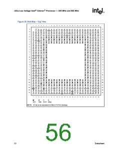
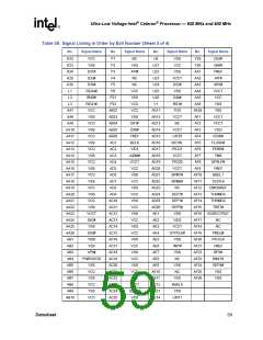
Figure 25 is a top-side view of the ball map of the ULV Intel® Celeron® processor with the voltage
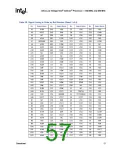
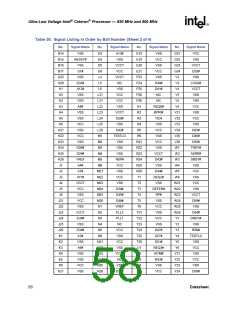
balls called out. Table 38 lists the signals in ball number order. Table 39 lists the signals in signal
name order.
Datasheet
55

 INTEL [ INTEL ]