Pin Listing and Signal Definitions
Table 37. Signal Description (Page 5 of 8)
Name
Type
Description
Input/
Output
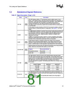
HIT# (Snoop Hit) and HITM# (Hit Modified) convey transaction snoop operation
results. Any system bus agent may assert both HIT# and HITM# together to
indicate that it requires a snoop stall, which can be continued by reasserting HIT#
and HITM# together.
HIT#
HITM#
IERR#
Input/
Output
IERR# (Internal Error) is asserted by a processor as the result of an internal error.
Assertion of IERR# is usually accompanied by a SHUTDOWN transaction on the
processor system bus. This transaction may optionally be converted to an external
error signal (e.g., NMI) by system core logic. The processor will keep IERR#
asserted until the assertion of RESET#.
Output
This signal does not have on-die termination and must be terminated on the
system board.
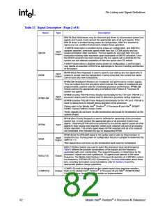
IGNNE# (Ignore Numeric Error) is asserted to force the processor to ignore a
numeric error and continue to execute noncontrol floating-point instructions. If
IGNNE# is deasserted, the processor generates an exception on a noncontrol
floating-point instruction if a previous floating-point instruction caused an error.
IGNNE# has no effect when the NE bit in control register 0 (CR0) is set.
IGNNE#
Input
IGNNE# is an asynchronous signal. However, to ensure recognition of this signal
following an Input/Output write instruction, it must be valid along with the TRDY#
assertion of the corresponding Input/Output Write bus transaction.
INIT# (Initialization), when asserted, resets integer registers inside the processor
without affecting its internal caches or floating-point registers. The processor then
begins execution at the power-on Reset vector configured during power-on
configuration. The processor continues to handle snoop requests during INIT#
assertion. INIT# is an asynchronous signal and must connect the appropriate pins
of all processor system bus agents.
INIT#
Input
If INIT# is sampled active on the active to inactive transition of RESET#, then the
processor executes its Built-in Self-Test (BIST).
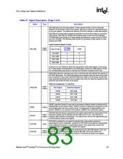
ITPCLKOUT[1:0] is an uncompensated differential clock output that is a delayed
copy of the BCLK[1:0], which is an input to the processor. This clock output can be
Output used as the differential clock into the ITP port that is designed onto the
motherboard. If ITPCLKOUT[1:0] outputs are not used, they must be terminated
properly. Refer to Section 2.5 for additional details and termination requirements.
ITPCLKOUT
[1:0]
ITP_CLK[1:0] are copies of BCLK that are used only in processor systems where
no debug port is implemented on the system board. ITP_CLK[1:0] are used as
ITP_CLK[1:0]
Input
BCLK[1:0] references for a debug port implemented on an interposer. If a debug
port is implemented in the system, ITP_CLK[1:0] are no connects in the system.
These are not processor signals.
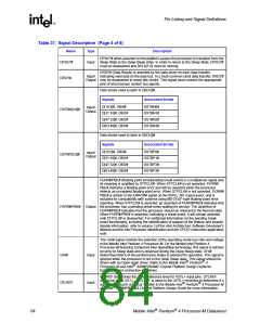
LINT[1:0] (Local APIC Interrupt) must connect the appropriate pins of all APIC Bus
agents. When the APIC is disabled, the LINT0 signal becomes INTR, a maskable
interrupt request signal, and LINT1 becomes NMI, a nonmaskable interrupt. INTR
and NMI are backward compatible with the signals of those names on the Pentium
processor. Both signals are asynchronous.
LINT[1:0]
Input
Both of these signals must be software configured via BIOS programming of the
APIC register space to be used either as NMI/INTR or LINT[1:0]. Because the APIC
is enabled by default after Reset, operation of these pins as LINT[1:0] is the default
configuration.
LOCK# indicates to the system that a transaction must occur atomically. This signal
must connect the appropriate pins of all processor system bus agents. For a locked
sequence of transactions, LOCK# is asserted from the beginning of the first
transaction to the end of the last transaction.
Input/
Output
LOCK#
When the priority agent asserts BPRI# to arbitrate for ownership of the processor
system bus, it will wait until it observes LOCK# deasserted. This enables symmetric
agents to retain ownership of the processor system bus throughout the bus locked
operation and ensure the atomicity of lock.
Mobile Intel Pentium 4 Processor-M Datasheet
85

 INTEL [ INTEL ]