System Bus Signal Quality Specifications
Table 29. Ringback Specifications for PWRGOOD Input and TAP Signal Groups
Maximum Ringback
(with Input Diodes Present)
Notes
Signal Group
Transition
Unit
Figure
TAP and PWRGOOD
TAP and PWRGOOD
0 → 1
1 → 0
Vt+(max) TO Vt-(max)
Vt-(min) TO Vt+(min)
V
V
28
29
1,2,3,4
1,2,3,4
NOTES:
1. All signal integrity specifications are measured at the processor silicon.
2. Unless otherwise noted, all specifications in this table apply to all Mobile Intel Pentium 4 Processor-M
frequencies.
3. Please see Section 3.3 for maximum allowable overshoot.
4. Please see Section 2.11 for the DC specifications.
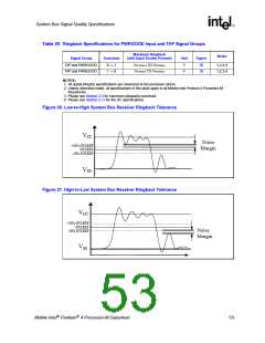
Figure 26. Low-to-High System Bus Receiver Ringback Tolerance
VCC
Noise
Margin
+10% GTLREF
GTLREF
-10% GTLREF
VSS
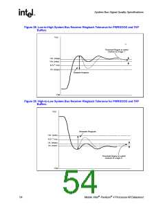
Figure 27. High-to-Low System Bus Receiver Ringback Tolerance
VCC
+10% GTLREF
GTLREF
-10% GTLREF
Noise
Margin
VSS
Mobile Intel Pentium 4 Processor-M Datasheet
53

 INTEL [ INTEL ]