Electrical Specifications
for the AGTL+ signal group traces is known and well-controlled. For more details on platform
design see the Mobile Intel Pentium 4 Processor-M and Intel 845MP/845MZ Chipset Platform
Design Guide.
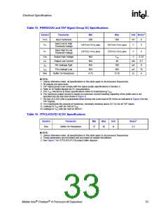
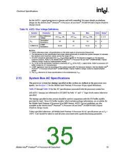
Table 18. AGTL+ Bus Voltage Definitions
Symbol
Parameter
Min
Typ
Max
Units Notes1
Bus Reference
Voltage
GTLREF
2/3 VCC -2%
2/3 VCC
2/3 VCC +2%
V
2, 3, 6
Termination
Resistance
RTT
45
50
51
55
Ω
Ω
4
5
COMP
Resistance
COMP[1:0]
50.49
51.51
NOTES:
1. Unless otherwise noted, all specifications in this table apply to all processor frequencies.
2. The tolerances for this specification have been stated generically to enable the system designer to calculate
the minimum and maximum values across the range of VCC
3. GTLREF should be generated from VCC by a voltage divider of 1% tolerance resistors or 1% tolerance
.
matched resistors. Refer to the Mobile Intel Pentium 4 Processor-M and Intel 845MP/845MZ Chipset
Platform Design Guide for implementation details.
4. RTT is the on-die termination resistance measured at VOL of the AGTL+ output driver. Refer to processor I/O
buffer models for I/V characteristics.
5. COMP resistance must be provided on the system board with 1% tolerance resistors. See the Mobile Intel
Pentium 4 Processor-M and Intel 845MP/845MZ Chipset Platform Design Guide for implementation
details.
6. The VCC referred to in these specifications is the instantaneous VCC
.
2.13
System Bus AC Specifications
The processor system bus timings specified in this section are defined at the processor core
(pads). See Section 5.2 for the Mobile Intel Pentium 4 Processor-M pin signal definitions.
Table 19 through Table 26 list the AC specifications associated with the processor system bus.
All AGTL+ timings are referenced to GTLREF for both “0” and “1” logic levels unless otherwise
specified.
The timings specified in this section should be used in conjunction with the I/O buffer models
provided by Intel. These I/O buffer models, which include package information, are available for
the Mobile Intel Pentium 4 Processor-M in IBIS format. AGTL+ layout guidelines are also
available in the Mobile Intel Pentium 4 Processor-M and Intel 845MP/845MZ Chipset
Platform Design Guide.
Unless specified otherwise, all Mobile Intel Pentium 4 Processor-M AC specifications are at T =
J
100°C. Care should be taken to read all notes associated with a particular timing parameter.
Mobile Intel Pentium 4 Processor-M Datasheet
35

 INTEL [ INTEL ]