Electrical Specifications
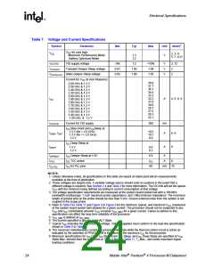
Table 7. Voltage and Current Specifications
Symbol
VCC
Parameter
Min
Typ
Max
Unit
Notes1
VCC for core logic
Maximum Performance Mode
Battery Optimized Mode
2, 3, 4,
5, 7, 8,11
1.3
1.2
V
VCCVID
VID supply voltage
-5%
0.91
0.95
1.2
+10%
1.09
V
V
V
2, 12
V
Transient Deeper Sleep voltage
Static Deeper Sleep voltage
Current for VCC at core frequency
1.00
1.00
2
2
CCDPRSLP
V
1.05
CCDPRSLP,DC
38.8
37.7
36.7
34.5
33.3
32.2
31.0
29.9
28.7
27.5
26.3
22.1
2.60 GHz & 1.3 V
2.50 GHz & 1.3 V
2.40 GHz & 1.3 V
2.20 GHz & 1.3 V
2.00 GHz & 1.3 V
1.90 GHz & 1.3 V
1.80 GHz & 1.3 V
1.70 GHz & 1.3 V
1.60 GHz & 1.3 V
1.50 GHz & 1.3 V
1.40 GHz & 1.3 V
1.20 GHz & 1.2 V
ICC
A
4, 5, 8, 9
IVCCVID
Current for VID supply
300
mA
A
ICC Stop-Grant and ICCSleep at
1.3 V (for > 2.0 GHz)
1.3 V (for <= 2.0 GHz)
1.2 V
10.5
10.1
8.9
ISGNT, ISLP
6, 9
9
ICC Deep Sleep at
IDSLP
A
1.3 V
1.2 V
9.0
8.3
IDPRSLP
ITCC
ICC Deeper Sleep at 1.0V
ICC TCC active
6.9
ICC
60
A
A
8
ICC PLL
ICC for PLL pins
mA
10
NOTES:
1. Unless otherwise noted, all specifications in this table are based on latest post-silicon measurements
available at the time of publication.
2. These voltages are targets only. A variable voltage source should exist on systems in the event that a
different voltage is required. See Section 2.4 and Table 3 for more information. The VID bits will set the typical
VCC with the minimum being defined according to current consumption at that voltage.
3. The voltage specification requirements are measured at the system board socket ball with a 100 MHz
bandwidth oscilloscope, 1.5 pF maximum probe capacitance, and 1 MΩ minimum impedance. The maximum
length of ground wire on the probe should be less than 5 mm. Ensure external noise from the system is not
coupled in the scope probe.
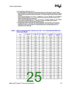
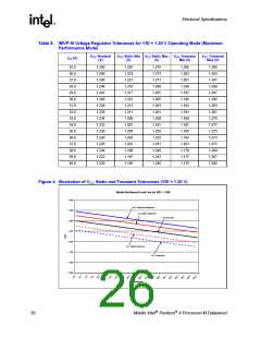
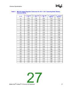
4. Refer to Table 8 to Table 11 and Figure 4 to Figure 6 for the minimum, typical, and maximum VCC (measured
at the system board socket ball) allowed for a given current. The processor should not be subjected to any
V
CC and ICC combination wherein VCC exceeds VCC_MAX for a given current. Failure to adhere to this
specification can affect the long term reliability of the processor.
5. VCC_MIN is defined at ICC_MAX
.
6. The current specified is also for AutoHALT State.
7. Typical VCC indicates the VID encoded voltage. Voltage supplied must conform to the load line specification
shown in Table 8 to Table 11.
8. The maximum instantaneous current the processor will draw while the thermal control circuit is active as
indicated by the assertion of PROCHOT# is the same as the maximum ICC for the processor.
9. Maximum specifications for ICC Core, ICC Stop-Grant, ICC Sleep, and ICC Deep Sleep are specified at VCC
Static Max. derived from the tolerances in Table 8 through Table 11, TJ Max., and under maximum signal
loading conditions.
24
Mobile Intel Pentium 4 Processor-M Datasheet

 INTEL [ INTEL ]