XMC1300
XMC1000 Family
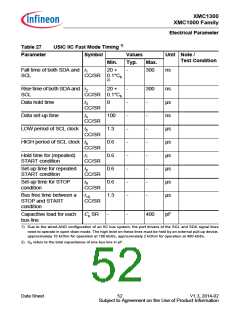
Electrical Parameter
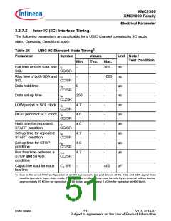
3.3.7
Peripheral Timings
Note: These parameters are not subject to production test, but verified by design and/or
characterization.
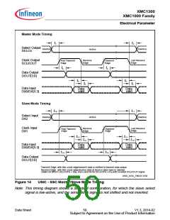
3.3.7.1 Synchronous Serial Interface (USIC SSC) Timing
The following parameters are applicable for a USIC channel operated in SSC mode.
Note: Operating Conditions apply.
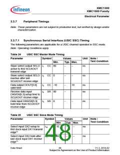
Table 24
USIC SSC Master Mode Timing
Symbol Values
Typ. Max.
Parameter
Unit Note /
Test Condition
Min.
Slave select output SELO t1 CC 80
active to first SCLKOUT
transmit edge
−
−
ns
Slave select output SELO t2 CC
inactive after last
0
−
−
ns
SCLKOUT receive edge
Data output DOUT[3:0]
valid time
t3 CC -10
t4 SR 80
−
−
10
ns
ns
Receive data input
−
DX0/DX[5:3] setup time to
SCLKOUT receive edge
Data input DX0/DX[5:3]
hold time from SCLKOUT
receive edge
t5 SR
0
−
−
ns
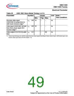
Table 25
USIC SSC Slave Mode Timing
Parameter
Symbol
Min.
Values
Unit Note /
Test Condition
Typ. Max.
Select input DX2 setup to
first clock input DX1 transmit
edge1)
t10 SR 10
−
−
ns
ns
Select input DX2 hold after t11 SR 10
last clock input DX1 receive
edge1)
−
−
Data Sheet
48
V1.3, 2014-02
Subject to Agreement on the Use of Product Information

 INFINEON [ Infineon ]