XMC1300
XMC1000 Family
Electrical Parameter
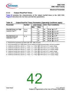
3.3.5
Serial Wire Debug Port (SW-DP) Timing
The following parameters are applicable for communication through the SW-DP
interface.
Note: These parameters are not subject to production test, but verified by design and/or
characterization.
Table 22
SWD Interface Timing Parameters(Operating Conditions apply)
Parameter
Symbol
Values
Unit Note /
Test Condition
Min.
50
Typ. Max.
SWDCLK high time
SWDCLK low time
t1 SR
t2 SR
t3 SR
–
–
–
500000 ns
500000 ns
–
–
–
50
SWDIO input setup
10
–
ns
to SWDCLK rising edge
SWDIO input hold
t4 SR
10
–
–
ns
–
after SWDCLK rising edge
SWDIO output valid time t5 CC
after SWDCLK rising edge
–
–
4
–
–
–
68
62
–
ns
ns
ns
CL = 50 pF
CL = 30 pF
SWDIO output hold time t6 CC
from SWDCLK rising edge
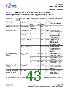
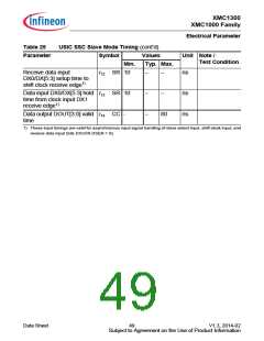
t1
t2
SWDCLK
t6
SWDIO
(Output)
t5
t3
t4
SWDIO
(Input )
Figure 13
SWD Timing
Data Sheet
46
V1.3, 2014-02
Subject to Agreement on the Use of Product Information

 INFINEON [ Infineon ]