XMC1300
XMC1000 Family
Electrical Parameter
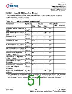
3.3.7.2 Inter-IC (IIC) Interface Timing
The following parameters are applicable for a USIC channel operated in IIC mode.
Note: Operating Conditions apply.
Table 26
USIC IIC Standard Mode Timing1)
Symbol Values
Parameter
Unit Note /
Test Condition
Min.
Typ.
Max.
Fall time of both SDA and t1
-
-
300
ns
ns
µs
ns
µs
µs
µs
µs
µs
µs
SCL
CC/SR
Rise time of both SDA and t2
-
-
-
-
-
-
-
-
-
-
1000
SCL
CC/SR
Data hold time
t3
0
-
-
-
-
-
-
-
-
CC/SR
Data set-up time
t4
250
4.7
4.0
4.0
4.7
4.0
4.7
CC/SR
LOW period of SCL clock t5
CC/SR
HIGH period of SCL clock t6
CC/SR
t7
CC/SR
Hold time for (repeated)
START condition
Set-up time for repeated t8
START condition
CC/SR
Set-up time for STOP
condition
t9
CC/SR
Bus free time between a t10
STOP and START
CC/SR
condition
Capacitive load for each
bus line
Cb SR
-
-
400
pF
1) Due to the wired-AND configuration of an IIC bus system, the port drivers of the SCL and SDA signal lines
need to operate in open-drain mode. The high level on these lines must be held by an external pull-up device,
approximalely 10 kOhm for operation at 100 kbit/s, approximately 2 kOhm for operation at 400 kbit/s.
Data Sheet
51
V1.3, 2014-02
Subject to Agreement on the Use of Product Information

 INFINEON [ Infineon ]