XMC1300
XMC1000 Family
Electrical Parameter
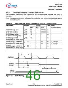
3.3.2
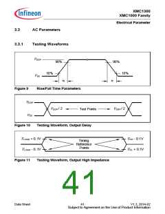
Output Rise/Fall Times
Table 18 provides the characteristics of the output rise/fall times in the XMC1300.
Figure 9 describes the rise time and fall time parameters.
Table 18
Output Rise/Fall Times Parameters (Operating Conditions apply)
Symbol Limit Values Unit Test Conditions
Parameter
Min.
Max.
9
Rise/fall times on High
Current Pad1)2)
tHCPR
tHCPF
,
–
–
–
–
–
–
ns
ns
ns
ns
ns
ns
50 pF @ 5 V3)
12
25
12
15
31
50 pF @ 3.3 V4)
50 pF @ 1.8 V5)
50 pF @ 5 V6)
50 pF @ 3.3 V7).
50 pF @ 1.8 V8).
Rise/fall times on
Standard Pad1)2)
tR, tF
1) Rise/Fall time parameters are taken with 10% - 90% of supply.
2) Not all parameters are 100% tested, but are verified by design/characterisation and test correlation.
3) Additional rise/fall time valid for CL = 50 pF - CL = 100 pF @ 0.150 ns/pF at 5 V supply voltage.
4) Additional rise/fall time valid for CL = 50 pF - CL = 100 pF @ 0.205 ns/pF at 3.3 V supply voltage.
5) Additional rise/fall time valid for CL = 50 pF - CL = 100 pF @ 0.445 ns/pF at 1.8 V supply voltage.
6) Additional rise/fall time valid for CL = 50 pF - CL = 100 pF @ 0.225 ns/pF at 5 V supply voltage.
7) Additional rise/fall time valid for CL = 50 pF - CL = 100 pF @ 0.288 ns/pF at 3.3 V supply voltage.
8) Additional rise/fall time valid for CL = 50 pF - CL = 100 pF @ 0.588 ns/pF at 1.8 V supply voltage.
Data Sheet
42
V1.3, 2014-02
Subject to Agreement on the Use of Product Information

 INFINEON [ Infineon ]