OPTIREG™ SBC TLE9274QXV33
High-speed CAN transceiver
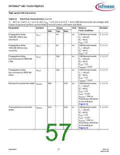
8.3
Electrical characteristics
Table 13 Electrical characteristics
Tj = -40°C to +150°C; VS = 5.5 V to 28 V; VCAN = 4.75 V to 5.25 V; RL = 60 Ω; CAN Normal mode; all voltages with
respect to ground, positive current flowing into pin (unless otherwise specified)
Parameter
Symbol
Values
Typ.
Unit Note or
Test Condition
Number
Min.
Max.
CAN supply voltage
CAN supply undervoltage
detection threshold
VCAN_UV
4.45
–
4.85
V
V
CAN Normal mode, P_8.3.1
hysteresis included
CAN bus receiver
Differential receiver
threshold voltage,
recessive to dominant edge
Vdiff,rd_N
–
0.80
0.90
8.0
–
Vdiff = VCANH - VCANL;
-12 V ≤ VCM(CAN) ≤
12 V;
P_8.3.2
CAN Normal mode
1)
Dominant state differential Vdiff_D_range 0.9
input voltage range
–
V
V
V
V
= VCANH - VCANL; P_8.3.50
diff
-12 V ≤ VCM(CAN) ≤
12 V;
CAN Normal mode
Differential receiver
threshold voltage,
dominant to recessive edge
Vdiff,dr_N
0.50
0.60
–
Vdiff = VCANH -VCANL
;
P_8.3.3
-12 V ≤ VCM(CAN) ≤
12 V;
CAN Normal mode
1)
Recessive state differential Vdiff_R_range -3.0
0.5
V
= VCANH - VCANL; P_8.3.51
diff
input voltage range
-12 V ≤ VCM(CAN) ≤
12 V;
CAN Normal mode
1)
Common mode range
CMR
-12
20
–
12
50
V
P_8.3.4
CANH, CANL input
resistance
Ri
40
kΩ
CAN Normal / Wake- P_8.3.5
capable mode;
Recessive state
-2 V ≤ VCANH/L ≤ +7 V
Differential input resistance Rdiff
40
80
100
kΩ
CAN Normal / Wake- P_8.3.6
capable mode;
Recessive state
-2 V ≤ VCANH/L ≤ +7 V
Input resistance deviation
between CANH and CANL
DRi
Cin
-3
–
–
3
%
1) Recessive state
CANH = VCANL = 5 V
P_8.3.7
P_8.3.8
P_8.3.42
V
2)
Input capacitance CANH,
CANL versus GND
20
10
40
20
pF
pF
V
= 5 V
TXDCAN
2)
Differential input
capacitance
Cdiff
–
V
= 5 V
TXDCAN
Datasheet
53
Rev.2.0
2022-05-06

 INFINEON [ Infineon ]