OPTIREG™ SBC TLE9274QXV33
High-speed CAN transceiver
•
•
The CAN transceiver mode must be toggled, i.e. switched from Wake-Capable mode to CAN Normal mode,
CAN Receive-Only mode or CAN Off, before switching to CAN Wake-Capable mode again
Rearming occurs automatically when the SBC changes to SBC Stop, or SBC Fail-Safe mode to ensure wake-
up capability
•
•
If the SBC is in SBC Stop mode, the CAN is rearmed automatically if the SBC is set again in SBC Stop mode
CAN must be set to CAN Wake-Capable or CAN OFF mode before entering SBC Sleep mode
Notes
1. It is necessary to clear the CAN wake-up bit CAN_WU to become wake capable again. It is sufficient to toggle
the CAN mode.
2. The CAN module is supplied by an internal voltage when in CAN Wake-Capable mode, i.e. the module must not
be supplied through the VCAN pin during this time. Before changing the CAN mode to Normal mode, the
supply of VCAN has to be activated first.
Wake-up in SBC Stop and Normal mode
In SBC Stop mode, if a wake-up pattern is detected, it is always signaled by the INT output and in the
WK_STAT_1 SPI register. It is also signaled by RXDCAN pulled to LOW. The same applies for the SBC Normal
mode. The microcontroller should set the device from SBC Stop mode to SBC Normal mode; there is no
automatic transition to Normal mode.
For functional safety reasons, the watchdog will be automatically enabled in SBC Stop mode after a bus wake-
up event in case it was disabled before (if bit WD_EN_WK_BUS was configured to HIGH before).
Wake-up in SBC Sleep mode
Wake-up is possible via a CAN message. The wake-up pattern automatically transfers the SBC into the
SBC Restart mode and from there to Normal mode the corresponding RXDCAN pin is set to LOW. The
microcontroller is able to detect the LOW signal on RXDCAN and to read the wake source out of the
WK_STAT_1 register via SPI. No interrupt is generated when coming out of Sleep mode. The microcontroller
can now, for example, switch the CAN transceiver into CAN Normal mode via SPI to start communication.
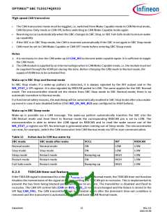
Table 12 Action due to CAN bus wake-Up
SBC mode
SBC mode after wake
Normal mode
Stop mode
VCC1
INT
RXDCAN
LOW
Normal mode
Stop mode
ON
LOW
LOW
HIGH
HIGH
HIGH
ON
LOW
Sleep mode
Restart mode
Fail-Safe mode
Restart mode
Restart mode
Restart mode
Ramping up
ON
LOW
LOW
Ramping up
LOW
8.2.5
TXDCAN time-out feature
If the TXDCAN signal is dominant for a time t > tTXDCAN_TO, in CAN Normal mode, the TXDCAN time-out function
disables the transmission of the signal at the bus, setting the TXDCAN pin to recessive. This is implemented to
prevent the bus from being blocked permanently due to an error. The transmitter is disabled and fixed to
recessive. The CAN SPI control bits (CAN on BUS_CTRL_1) remain unchanged and the failure is stored in the
SPI flag CAN_FAIL. The CAN transmitter stage is activated again after the dominant time-out condition is
removed and the transceiver is automatically switched back to CAN Normal mode.
Datasheet
51
Rev.2.0
2022-05-06

 INFINEON [ Infineon ]