TLE9263QX
External Voltage Regulator 3
VS
VCC13
RSHUNT
T1
ICC3
C1
C2
VS
VCC3SH
VCC3B
VCC3REF
Vcc3
Vcc1
ICC1
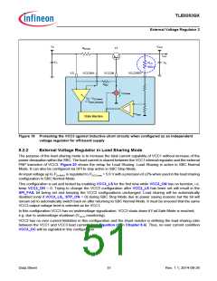
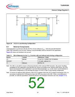
Figure 20 VCC3 in Load Sharing Configuration
8.3
External Components
Characterization is performed with the BCP52-16 from Infineon (ICC3 < 200 mA) and with MJD253.
Other PNP transistors can be used. However, the functionality must be checked in the application.
Figure 20 shows one hardware set up used.
Table 13
Device
C2
Bill of Materials for the VCC3 Function with and without load sharing configuration
Vendor
Murata
-
Reference / Value
10 µF/10 V GCM31CR71A106K64L
1 ꢀ (with / without LS)
BCP52-16
RSHUNT
T1
Infineon
Note:The SBC is not able to ensure a thermal protection of the external PNP transistor. The power handling
capabilities for the application must therefore be chosen according to the selected PNP device, the PCB
layout and properties of the application to prevent thermal damage, e.g. via the shunt current limitation in
stand alone configuration or by selecting the proper ICC1/ICC3 ratio in load-sharing configuration.
Note:To ensure an optimum EMC behavior of the VCC3 regulator when the VCC3 output is leaving the PCB, it is
necessary to optimize the PCB layout to have the PNP very close to the SBC. If this is not sufficient or
possible, an external capacitance should be placed to the off-board connector (see also Chapter 17.1).
Data Sheet
52
Rev. 1.1, 2014-09-26

 INFINEON [ Infineon ]