TLE9263QX
External Voltage Regulator 3
VS
VCC3
RSHUNT
T1
ICC3
C2
C1
RLim
100Ω
VS
VCC3SH
VCC3B
RBE
VCC3REF
ICC3base
VS - VCC3shunt
> Vshunt_threshold
+
-
VREF
State Machine
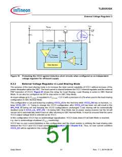
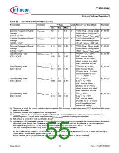
Figure 19 Protecting the VCC3 against inductive short circuits when configured as an independent
voltage regulator for off-board supply
8.2.2
External Voltage Regulator in Load Sharing Mode
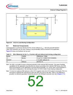
The purpose of the load sharing mode is to increase the total current capability of VCC1 without increase of the
power dissipation within the SBC. The load current is shared between the VCC1 internal regulator and the external
PNP transistor of VCC3. Figure 20 shows the setup for Load Sharing. Load Sharing is active in SBC Normal
Mode. It can also be configured via SPI to stay active in SBC Stop Mode.
An input voltage up to VSx,MAX is regulated to VCC3,nom = 5.0 V with a precision of ±2% when used in the load sharing
configuration in SBC Normal Mode.
This configuration is set and locked by enabling VCC3_LS for the first time while VCC3_ON has no function, i.e.
keep VCC3_ON = 0. Trying to change the VCC3 configuration after VCC3_LS has been set will result in the
SPI_FAIL bit being set and keeping the VCC3 configurations unchanged. Load sharing will be automatically
disabled (only if VCC3_LS_ STP_ON = 0) during SBC Stop Mode due to power saving reasons but the bit will
remain set to automatically switch back on after returning to SBC Normal Mode. It must be ensured that the same
VCC3 output voltage level is selected as for VCC1.
In this configuration VCC3 has no undervoltage signalization. VCC3 shuts down if Fail-Safe Mode is reached,
e.g. due to undervoltage shutdown (VS,UV monitoring).
VCC3 has no over current limitation in this configuration and the shunt resistor is defining the load sharing ratio
between the VCC1 and VCC3 load currents (see Equation (2) in Chapter 8.4). Thus, no over current condition
VCC3_OC will be signaled in this configuration.
Data Sheet
51
Rev. 1.1, 2014-09-26

 INFINEON [ Infineon ]