TLE9263QX
System Features
5
System Features
This chapter describes the system features and behavior of the TLE9263QX:
•
•
•
•
•
•
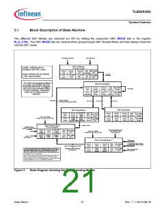
State machine
SBC mode control
Device configuration
State of supply and peripherals
System functions such as cyclic sense or cyclic wake
Supervision and diagnosis functions
The System Basis Chip (SBC) offers six operating modes:
•
•
•
•
•
SBC Init Mode: Power-up of the device and after a soft reset,
SBC Normal Mode: The main operating mode of the device,
SBC Stop Mode: The first-level power saving mode with the main voltage regulator VCC1 enabled,
SBC Sleep Mode: The second-level power saving mode with VCC1 disabled,
SBC Restart Mode: An intermediate mode after a wake event from SBC Sleep or Fail-Safe Mode or after a
failure (e.g. WD failure, VCC1 under voltage reset) to bring the microcontroller into a defined state via a reset.
Once the failure condition is not present anymore the device will automatically change to SBC Normal Mode
after a delay time (tRD1).
•
SBC Fail-Safe Mode: A safe-state mode after critical failures (e.g. WD failure, VCC1 under voltage reset) to
bring the system into a safe state and to ensure a proper restart of the system. VCC1 is disabled. It is a
permanent state until either a wake event (via CAN, LINx or WKx) occurs or the over temperature condition is
not present anymore.
A special mode, called SBC Development Mode, is available during software development or debugging of the
system. All above mentioned operating modes can be accessed in this mode. However, the watchdog counter is
stopped and does not need to be triggered. This mode can be accessed by setting the TEST pin to GND during
SBC Init Mode.
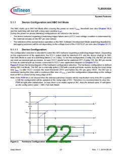
The device can be configured via hardware (external component) to determine the device behavior after a
watchdog trigger failure. See Chapter 5.1.1 for further information.
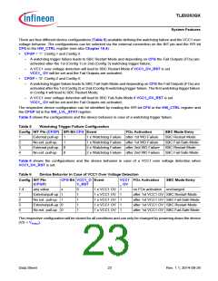
The System Basis Chip is controlled via a 16-bit SPI interface. A detailed description can be found in
Chapter 16.The configuration as well as the diagnosis is handled via the SPI. The SPI mapping of the TLE9263QX
is compatible to other devices of the TLE926x and TLE927x families.
Data Sheet
20
Rev. 1.1, 2014-09-26

 INFINEON [ Infineon ]