TLD7002-16ES
Datasheet
9 Communication interface
Table 42
(continued) Bit field description
Bits Type Description
Field
OUT_SHORT_WRN
6
r
short between adjacent output warning
0 .. no short between adjacent output warning detected
1 .. there was at least one short between an adjacent output warning
detected
GPINn_WRN
DC_WRN
CUR_WRN
VFWD_WRN
OVLD
5
4
3
2
1
0
r
r
r
r
r
r
GPINn warning flag
0 ... GPIN0 and GPIN1 are not in a fault condition
1 ... there was at least one GPINn fault condition
Duty cycle warning flag
0 ... no duty cycle warning for OUT0 to OUT15 detected
1 ... there was at least one duty cycle warning condition
Output current warning flag
0 ... no output current warning for OUT0 to OUT15 detected
1 ... there was at least one output current warning condition
Forward voltage warning flag
0 ... no forward voltage warning for OUT0 to OUT15 detected
1 ... there was at least one forward voltage warning condition
Over load flag
0 ... no thermal overload condition detected on OUT0 to OUT15
1 ... there was at least one thermal overload condition detected
Fault
Internal fault flag
0 ... no internal fault detected
1 ... internal fault condition detected
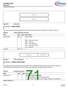
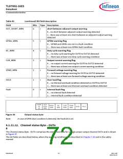
Figure 36
Output status byte
In case of GPIN short condition is detected, the Fault bit is set.
Note:
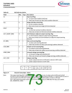
9.1.11.12. Channel status Byte – OUTn
8
The Channel status Byte - OUTn comprises the status overview for a single power output channel OUTn and is shown
in Figure 37.
The bit fields are described below, where the warning conditions are described in Chapter 7.10 and in the safety
manual
Datasheet
72
Rev.1.00
2022-05-03

 INFINEON [ Infineon ]