TLD7002-16ES
Datasheet
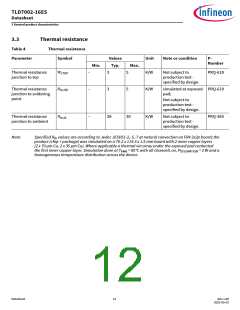
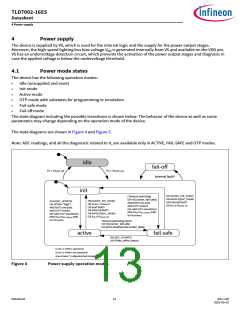
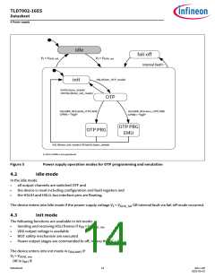
4 Power supply
Valid commands means no CRC-3 for master request, CRC-8 error and no frame structure error occurred.
4.7
OTP mode
In this mode the LCU can program or emulate the OTP configuration.
Following functions are available in OTP mode:
•
•
•
Sending and receiving HSLI frames if VDD > VDD(UV)_rise
VDD output voltage is available
internal fault monitoring
The device enters into OTP mode in tINIT2OTP if:
•
•
the device is in init mode AND
the device received a valid enter_OTP_mode frame via the HSLI bus
4.8
OTP programming mode
The following functions are available in OTP programming mode:
•
•
•
sending and receiving HSLI frames if VDD > VDD(UV)_rise
VDD output voltage is available
internal fault monitoring
The device enters into OTP programming mode in tOTP2PRG if:
•
•
•
the device is in OTP mode AND
the device received a WRITE_REG(write_OTP) via the HSLI bus AND
GPIN0 is set to “high”.
In this programing mode the LCU can program the OTP configuration register and store them permanently in the OTP.
In order to program the OTP, supply voltage on VS pin must remain within the VS_PROG voltage range during the
entire programming procedure. The OTP is locked and secured if the LCU successfully writes all the OTP registers and
the correct CRC protection word.
Note:
In case GPIN0=LOW and a valid passphrase is sent, the device remains in OTP mode. A HSLI power mode
change frame is required to move the device to init mode.
4.9
OTP programming emulation mode
The following functions are available in OTP programming emulation mode:
•
•
•
sending and receiving HSLI frames if VDD > VDD(UV)_rise
VDD output voltage is available
internal fault monitoring
The device enters into OTP programming emulation mode in tOTP2PRG if:
•
•
•
the device is in OTP mode AND
the device received a WRITE_REG(emu_OTP) via the HSLI bus AND
GPIN0 is set as digital input and a “high” voltage level applied.
In this emulation mode the LCU can program a volatile copy of the OTP.
Datasheet
16
Rev.1.00
2022-05-03

 INFINEON [ Infineon ]