TC1796
Electrical Parameters
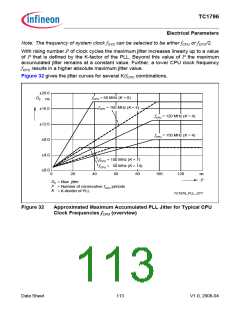
Note: The frequency of system clock fSYS can be selected to be either fCPU or fCPU/2.
With rising number P of clock cycles the maximum jitter increases linearly up to a value
of P that is defined by the K-factor of the PLL. Beyond this value of P the maximum
accumulated jitter remains at a constant value. Further, a lower CPU clock frequency
f
CPU results in a higher absolute maximum jitter value.
Figure 32 gives the jitter curves for several K/fCPU combinations.
±20.0
fCPU = 50 MHz (K = 8)
fCPU = 100 MHz (K = 4)
DP
ns
±16.0
±12.0
±8.0
±4.0
±0.0
fCPU = 120 MHz (K = 4)
fCPU = 150 MHz (K = 4)
fCPU = 100 MHz (K = 7)
fCPU = 50 MHz (K = 14)
0
20
40
60
80
100
120
oo
P
DP
= Max. jitter
P
= Number of consecutive fCPU periods
K
= K-divider of PLL
TC1976_PLL_JITT
Figure 32
Approximated Maximum Accumulated PLL Jitter for Typical CPU
Clock Frequencies fCPU (overview)
Data Sheet
113
V1.0, 2008-04

 INFINEON [ Infineon ]