C167CR
C167SR
Interrupt System
With an interrupt response time within a range from just 5 to 12 CPU clocks (in case of
internal program execution), the C167CR is capable of reacting very fast to the
occurrence of non-deterministic events.
The architecture of the C167CR supports several mechanisms for fast and flexible
response to service requests that can be generated from various sources internal or
external to the microcontroller. Any of these interrupt requests can be programmed to
being serviced by the Interrupt Controller or by the Peripheral Event Controller (PEC).
In contrast to a standard interrupt service where the current program execution is
suspended and a branch to the interrupt vector table is performed, just one cycle is
‘stolen’ from the current CPU activity to perform a PEC service. A PEC service implies a
single byte or word data transfer between any two memory locations with an additional
increment of either the PEC source or the destination pointer. An individual PEC transfer
counter is implicitly decremented for each PEC service except when performing in the
continuous transfer mode. When this counter reaches zero, a standard interrupt is
performed to the corresponding source related vector location. PEC services are very
well suited, for example, for supporting the transmission or reception of blocks of data.
The C167CR has 8 PEC channels each of which offers such fast interrupt-driven data
transfer capabilities.
A separate control register which contains an interrupt request flag, an interrupt enable
flag and an interrupt priority bitfield exists for each of the possible interrupt sources. Via
its related register, each source can be programmed to one of sixteen interrupt priority
levels. Once having been accepted by the CPU, an interrupt service can only be
interrupted by a higher prioritized service request. For the standard interrupt processing,
each of the possible interrupt sources has a dedicated vector location.
Fast external interrupt inputs are provided to service external interrupts with high
precision requirements. These fast interrupt inputs feature programmable edge
detection (rising edge, falling edge or both edges).
Software interrupts are supported by means of the ‘TRAP’ instruction in combination with
an individual trap (interrupt) number.
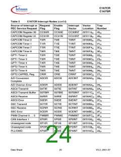
Table 3 shows all of the possible C167CR interrupt sources and the corresponding
hardware-related interrupt flags, vectors, vector locations and trap (interrupt) numbers.
Note: Interrupt nodes which are not used by associated peripherals, may be used to
generate software controlled interrupt requests by setting the respective interrupt
request bit (xIR).
Data Sheet
18
V3.2, 2001-07

 INFINEON [ Infineon ]