C167CR
C167SR
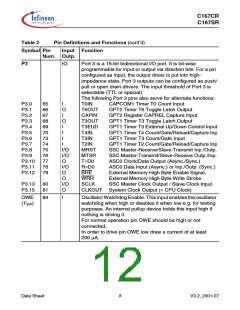
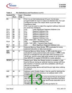
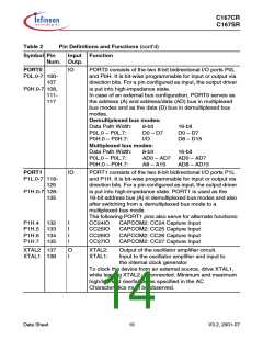
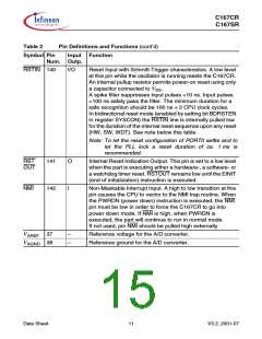
Table 2
Pin Definitions and Functions (cont’d)
Symbol Pin
Input Function
Num. Outp.
VDD
17, 46, –
Digital Supply Voltage:
56, 72,
82, 93,
109,
+5 V during normal operation and idle mode.
≥2.5 V during power down mode.
126,
136,
144
VSS
18, 45, –
55, 71,
83, 94,
110,
Digital Ground.
127,
139,
143
Note: The following behavioural differences must be observed when the bidirectional
reset is active:
• Bit BDRSTEN in register SYSCON cannot be changed after EINIT and is cleared
automatically after a reset.
• The reset indication flags always indicate a long hardware reset.
• The PORT0 configuration is treated as if it were a hardware reset. In particular, the
bootstrap loader may be activated when P0L.4 is low.
• Pin RSTIN may only be connected to external reset devices with an open drain output
driver.
• A short hardware reset is extended to the duration of the internal reset sequence.
Data Sheet
12
V3.2, 2001-07

 INFINEON [ Infineon ]