C167CR
PWM Module
The Pulse Width Modulation Module can generate up to four PWM output signals using edge-
aligned or center-aligned PWM. In addition the PWM module can generate PWM burst signals and
single shot outputs. The frequency range of the PWM signals covers 4.8 Hz to 1 MHz (referred to
a CPU clock of 20 MHz), depending on the resolution of the PWM output signal. The level of the
output signals is selectable and the PWM module can generate interrupt requests.
General Purpose Timer (GPT) Unit
The GPT unit represents a very flexible multifunctional timer/counter structure which may be used
for many different time related tasks such as event timing and counting, pulse width and duty cycle
measurements, pulse generation, or pulse multiplication.
The GPT unit incorporates five 16-bit timers which are organized in two separate modules, GPT1
and GPT2. Each timer in each module may operate independently in a number of different modes,
or may be concatenated with another timer of the same module.
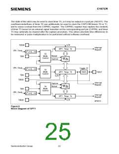
Each of the three timers T2, T3, T4 of module GPT1 can be configured individually for one of three
basic modes of operation, which are Timer, Gated Timer, and Counter Mode. In Timer Mode, the
input clock for a timer is derived from the CPU clock, divided by a programmable prescaler, while
Counter Mode allows a timer to be clocked in reference to external events.
Pulse width or duty cycle measurement is supported in Gated Timer Mode, where the operation of
a timer is controlled by the ‘gate’ level on an external input pin. For these purposes, each timer has
one associated port pin (TxIN) which serves as gate or clock input. The maximum resolution of the
timers in module GPT1 is 400 ns (@ 20-MHz CPU clock).
The count direction (up/down) for each timer is programmable by software or may additionally be
altered dynamically by an external signal on a port pin (TxEUD) to facilitate e. g. position tracking.
Timers T3 and T4 have output toggle latches (TxOTL) which change their state on each timer over-
flow/underflow. The state of these latches may be output on port pins (TxOUT) e. g. for time out
monitoring of external hardware components, or may be used internally to clock timers T2 and T4
for measuring long time periods with high resolution.
In addition to their basic operating modes, timers T2 and T4 may be configured as reload or capture
registers for timer T3. When used as capture or reload registers, timers T2 and T4 are stopped. The
contents of timer T3 is captured into T2 or T4 in response to a signal at their associated input pins
(TxIN). Timer T3 is reloaded with the contents of T2 or T4 triggered either by an external signal or
by a selectable state transition of its toggle latch T3OTL. When both T2 and T4 are configured to
alternately reload T3 on opposite state transitions of T3OTL with the low and high times of a PWM
signal, this signal can be constantly generated without software intervention.
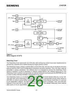
With its maximum resolution of 200 ns (@ 20 MHz), the GPT2 module provides precise event
control and time measurement. It includes two timers (T5, T6) and a capture/reload register
(CAPREL). Both timers can be clocked with an input clock which is derived from the CPU clock via
a programmable prescaler or with external signals. The count direction (up/down) for each timer is
programmable by software or may additionally be altered dynamically by an external signal on a
port pin (TxEUD). Concatenation of the timers is supported via the output toggle latch (T6OTL) of
timer T6, which changes its state on each timer overflow/underflow.
Semiconductor Group
21

 INFINEON [ Infineon ]