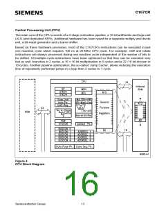
C167CR
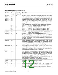
Pin Definitions and Functions (cont’d)
Symbol Pin Input (I) Function
Number Output (O)
PORT1:
P1L.0 -
P1L.7,
P1H.0 - 128 -
P1H.7
I/O
118 -
125
PORT1 consists of the two 8-bit bidirectional I/O ports P1L
and P1H. It is bit-wise programmable for input or output via
direction bits. For a pin configured as input, the output driver
is put into high-impedance state. PORT1 is used as the 16-bit
address bus (A) in demultiplexed bus modes and also after
switching from a demultiplexed bus mode to a multiplexed bus
mode.
135
The following PORT1 pins also serve for alternate functions:
132
133
134
135
I
I
I
I
P1H.4
P1H.5
P1H.6
P1H.7
CC24IO CAPCOM2: CC24 Capture Input
CC25IO CAPCOM2: CC25 Capture Input
CC26IO CAPCOM2: CC26 Capture Input
CC27IO CAPCOM2: CC27 Capture Input
XTAL1
XTAL2
138
I
XTAL1:
Input to the oscillator amplifier and input to the
internal clock generator
Output of the oscillator amplifier circuit.
137
O
XTAL2:
To clock the device from an external source, drive XTAL1,
while leaving XTAL2 unconnected. Minimum and maximum
high/low and rise/fall times specified in the AC Characteristics
must be observed.
RSTIN
140
I
Reset Input with Schmitt-Trigger characteristics. A low level at
this pin for a specified duration while the oscillator is running
resets the C167CR. An internal pullup resistor permits power-
on reset using only a capacitor connected to VSS.
RSTOUT 141
O
I
Internal Reset Indication Output. This pin is set to a low level
when the part is executing either a hardware-, a software- or a
watchdog timer reset. RSTOUT remains low until the EINIT
(end of initialization) instruction is executed.
NMI
142
Non-Maskable Interrupt Input. A high to low transition at this
pin causes the CPU to vector to the NMI trap routine. When
the PWRDN (power down) instruction is executed, the NMI
pin must be low in order to force the C167CR to go into power
down mode. If NMI is high, when PWRDN is executed, the
part will continue to run in normal mode.
If not used, pin NMI should be pulled high externally.
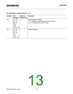
VAREF
VAGND
VPP
37
38
84
–
–
–
Reference voltage for the A/D converter.
Reference ground for the A/D converter.
Flash programming voltage. This pin accepts the
programming voltage for flash versions of the C167CR.
Note: This pin is not connected (NC) on non-flash versions.
Semiconductor Group
9

 INFINEON [ Infineon ]