PEB 2091
PEF 2091
Electrical Characteristics
8
Electrical Characteristics
This chapter specifies on the one hand the electrical characteristics of device inputs and
power needed to guarantee proper operation of the IEC-Q. On the other hand it specifies
the electrical characteristics of the IEC-Q outputs, power consumption and analog
functions.
Note 76: All electrical characteristics of the IEC-Q apply only in the specified
operational range and under the stated test conditions.
Sections 8.1 and 8.2 describe the maximum ratings allowed and the power supply
needed.
Section 8.3 specifies the maximal overload which can be imposed directly on the IEC-Q
line interface, without causing device damage.
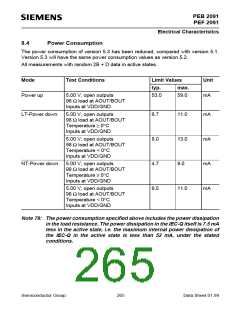
Sections 8.4 and 8.5 specify the power consumption and the analog functions (e.g. ADC
and DAC performance).
Section 8.6 describes the DC characteristics of the IEC-Q.
The dynamic characteristics of the microprocessor interface, the IOM®-2 interface, the
power controller interface, the undervoltage detection block and device clock are given
in section 8.7.
8.1
Absolute Maximum Ratings
Parameter
Symbol Limit Values
VDD – 0.3 < VDD < 7.0
Unit
Supply voltage
Input voltage
Output voltage
V
VI
– 0.3 < VI < VDD + 0.3 (max. 7) V
– 0.3 < VO < VDD + 0.3 (max 7) V
– 0.3 < VS < VDD + 0.3 (max. 7) V
VO
Max. voltage applied at U-Interface VS
Max. voltage between
GNDA1 (GNDA2) and GNDD
VS
± 250
mV
Storage temperature
Tstg
– 65 to 125
° C
Ambient temperature
PEB 2091
PEF 2091
TA
TA
0 to 70
– 40 to 85
° C
° C
Thermal resistance
(system-air)
(system-case)
Rth SA
Rth SC
40
9
K/W
K/W
Semiconductor Group
262
Data Sheet 01.99

 INFINEON [ Infineon ]