IMW120R140M1H
CoolSiC™ 1200V SiC Trench MOSFET
Electrical characteristic diagrams
90
80
70
60
50
40
30
20
10
0
400
td(on)
tr
Etot
Eon
td(off)
tf
Eoff
300
200
100
0
0
20 40 60 80 100 120
RG [Ohm]
0
20 40 60 80 100 120
RG [Ohm]
Figure 18 Typical switching times as a function of
gate resistor
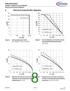
Figure 17 Typical switching energy losses as a
function of gate resistance
(t = f(RG,ext), VDD = 800V, VGS = 0V/18V,
ID = 6A, Tvj = 175°C, ind. load, test circuit in
Fig. E, diode: body diode at VGS = 0V)
(E = f(RG,ext), VDD = 800V, VGS = 0V/18V,
ID = 6A, Tvj = 175°C, ind. load, test circuit in
Fig. E, diode: body diode at VGS = 0V)
0.4
0.3
0.2
10
175°C
25°C
8
6
4
2
0
0.1
175°C
25°C
0.0
0
2000
4000
6000
0
2000
4000
6000
diF /dt[A/µs]
diF /dt[A/µs]
Figure 19 Typical reverse recovery charge as a
function of diode current slope
(Qrr = f(dif/dt), VDD = 800V, VGS = 0V/18V,
ID = 6A, ind. load, test circuit in Fig.E, body
diode at VGS = 0V)
Figure 20 Typical reverse recovery current as a
function of diode current slope
(Irrm = f(dif/dt), VDD = 800V, VGS = 0V/18V,
ID = 6A, ind. load, test circuit in Fig.E,
body diode at VGS = 0V)
Datasheet
12 of 17
2.2
2020-12-11

 INFINEON [ Infineon ]