CoolSET™-F2
ICE2A165/265/365
ICE2A180/280
Functional Description
3
Functional Description
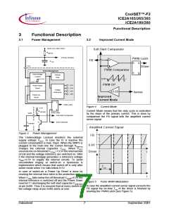
3.1
Power Management
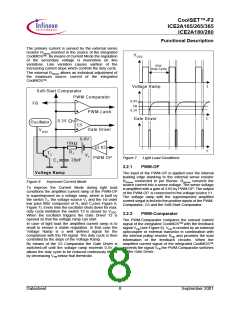
3.2
Improved Current Mode
M ain Line (100V-380V)
RStart-Up
Soft-Start Com parator
Prim ary W inding
PW M -Latch
FB
C VCC
R
Q
VCC
Driver
PW M Com parator
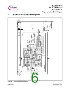
Power Management
S
Q
Undervoltage
Internal
Lockout
Bias
13.5V
0.8V
8.5V
PW M O P
6.5V
Power-Down
Reset
5.3V
4.8V
4.0V
Voltage
x3.65
Reference
Isense
Power-Up
Reset
Improved
Current Mode
R
S
Q
Q
PW M-Latch
Figure 4
Current Mode
6.5V
R Soft-Start
Current Mode means that the duty cycle is controlled
by the slope of the primary current. This is done by
comparison the FB signal with the amplified current
sense signal.
Error-Latch
SoftS
Soft-Start C om parator
Error-Detection
T1
CSoft-Start
Am plified Current Signal
FB
Figure 3
Power Management
The Undervoltage Lockout monitors the external
supply voltage VVCC. In case the IC is inactive the
current consumption is max. 55µA. When the SMPS is
plugged to the main line the current through RStart-up
charges the external Capacitor CVCC. When VVCC
exceeds the on-threshold VCCon=13.5V the internal bias
circuit and the voltage reference are switched on. After
it the internal bandgap generates a reference voltage
0.8V
Driver
t
t
V
REF=6.5V to supply the internal circuits. To avoid
uncontrolled ringing at switch-on a hysteresis is
implemented which means that switch-off is only after
active mode when Vcc falls below 8.5V.
Ton
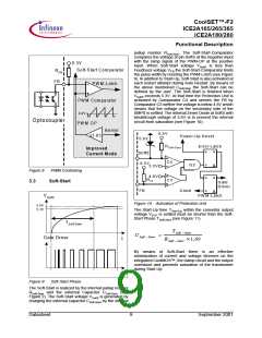
In case of switch-on a Power Up Reset is done by
reseting the internal error-latch in the protection unit.
When VVCC falls below the off-threshold VCCoff=8.5V the
internal reference is switched off and the Power Down
reset let T1 discharging the soft-start capacitor CSoft-Start
at pin SoftS. Thus it is ensured that at every switch-on
the voltage ramp at pin SoftS starts at zero.
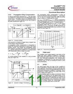
Figure 5
Pulse Width Modulation
In case the amplified current sense signal exceeds the
FB signal the on-time Ton of the driver is finished by
reseting the PWM-Latch (see Figure 5).
Datasheet
7
September 2001

 INFINEON [ Infineon ]