CoolSET™-F2
ICE2A165/265/365
ICE2A180/280
Pin Configuration and Functionality
1
Pin Configuration and Functionality
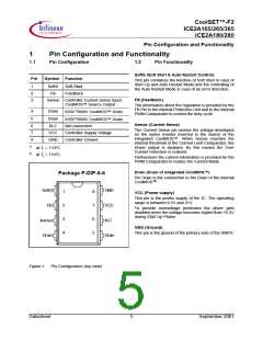
1.1
Pin Configuration
1.2
Pin Functionality
SoftS (Soft Start & Auto Restart Control)
Pin
Symbol Function
This pin combines the function of Soft Start in case of
Start Up and Auto Restart Mode and the controlling of
the Auto Restart Mode in case of an error detection.
1
2
3
SoftS
FB
Soft-Start
Feedback
FB (Feedback)
Isense Controller Current Sense Input,
CoolMOS™ Source Output
The information about the regulation is provided by the
FB Pin to the internal Protection Unit and to the internal
PWM-Comparator to control the duty cycle.
650V1)/800V CoolMOS™ Drain
Drain
4
5
650V2)/800V CoolMOS™ Drain
Drain
Isense (Current Sense)
6
7
8
N.C
VCC
GND
Not connected
The Current Sense pin senses the voltage developed
on the series resistor inserted in the source of the
integrated CoolMOS™. When Isense reaches the
internal threshold of the Current Limit Comparator, the
Driver output is disabled. By this means the Over
Current Detection is realized.
Controller Supply Voltage
Controller Ground
1)
2)
at Tj = 110°C
at Tj = 110°C
Furthermore the current information is provided for the
PWM-Comparator to realize the Current Mode.
Drain (Drain of integrated CoolMOS™)
Package P-DIP-8-6
Pin Drain is the connection to the Drain of the internal
CoolMOSTM
.
SoftS
FB
GND
VCC
N.C
1
2
3
4
8
7
6
5
VCC (Power supply)
This pin is the positiv supply of the IC. The operating
range is between 8.5V and 21V.
To provide overvoltage protection the driver gets
disabled when the voltage becomes higher than 16.5V
during Start Up Phase.
Isense
Drain
GND (Ground)
This pin is the ground of the primary side of the SMPS.
Drain
Figure 1
Pin Configuration (top view)
Datasheet
5
September 2001

 INFINEON [ Infineon ]