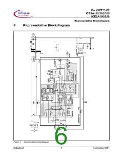
CoolSET™-F2
ICE2A165/265/365
ICE2A180/280
Functional Description
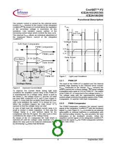
kHz
100
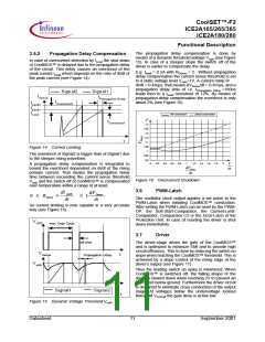
VSoftS
5.3V
65
TSoft-Start
21,5
0,9
VFB
t
t
1,0
1,1
1,2
1,3
1,4
1,5
1,6
1,7
1,8
1,9
2
V
VFB
4.8V
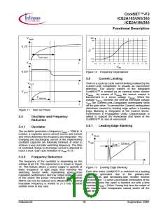
Figure 12 Frequency Dependence
3.5
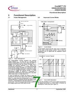
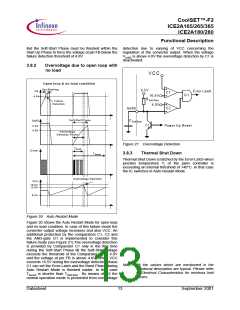
Current Limiting
VO UT
There is a cycle by cycle current limiting realised by the
Current-Limit Comparator to provide an overcurrent
detection. The source current of the integrated
CoolMOSTM is sensed via an external sense resistor
RSense . By means of RSense the source current is
transformed to a sense voltage VSense. When the
voltage VSense exceeds the internal threshold voltage
Vcsth the Current-Limit-Comparator immediately turns
off the gate drive. To prevent the Current Limiting from
distortions caused by leading edge spikes a Leading
Edge Blanking is integrated at the Current Sense.
Furthermore a Propagation Delay Compensation is
added to support the immedeate shut down of the
CoolMOS™ in case of overcurrent.
VO UT
TStart-Up
t
Figure 11 Start Up Phase
3.4
Oscillator and Frequency
Reduction
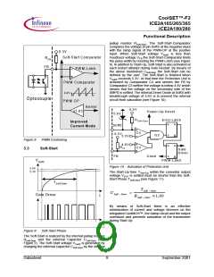
3.5.1
Leading Edge Blanking
3.4.1
Oscillator
The oscillator generates a frequency fswitch = 100kHz. A
resistor, a capacitor and a current source and current
sink which determine the frequency are integrated. The
charging and discharging current of the implemented
oscillator capacitor are internally trimmed, in order to
achieve a very accurate switching frequency. The ratio
of controlled charge to discharge current is adjusted to
reach a max. duty cycle limitation of Dmax=0.72.
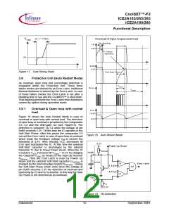
VSense
Vcsth
tLEB = 220ns
3.4.2
Frequency Reduction
The frequency of the oscillator is depending on the
voltage at pin FB. The dependence is shown in Figure
12. This feature allows a power supply to operate at
lower frequency at light loads thus lowering the
switching losses while maintaining good cross
regulation performance and low output ripple. In case
of low power the power consumption of the whole
SMPS can now be reduced very effective. The minimal
reachable frequency is limited to 21.5 kHz to avoid
audible noise in any case.
t
Figure 13 Leading Edge Blanking
Each time when CoolMOS™ is switched on a leading
spike is generated due to the primary-side
capacitances and secondary-side rectifier reverse
recovery time. To avoid a premature termination of the
switching pulse this spike is blanked out with a time
constant of tLEB = 220ns. During that time the output of
the Current-Limit Comparator cannot switch off the
gate drive.
Datasheet
10
September 2001

 INFINEON [ Infineon ]