AIROC™ Bluetooth® system on chip for automotive applications
Specifications
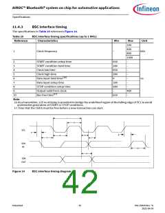
11.3
RF specifications
Note Table 22 and Table 23 apply to single-ended industrial temperatures. Unused inputs are left open.
Table 22
BR/EDR - Receiver RF specifications
Mode and conditions
Parameter
Min
Typ
Max
Unit
Receiver section
Frequency range
–
2402
–
–
–
–20
–
2480
MHz
dBm
GFSK, BDR GFSK 0.1% BER, 1 Mbps
–91[9]
–94
–
–
–
–
RX sensitivity
EDR 2M
EDR 3M
–
dB
–87.5
–
Maximum input
dBm
Interference performance
C/I cochannel
C/I 1 MHz adjacent channel
C/I 2 MHz adjacent channel
C/I 3 MHz adjacent channel
C/I image channel
GFSK, BDR GFSK 0.1% BER[10]
GFSK, BDR GFSK 0.1% BER[10]
GFSK, BDR GFSK 0.1% BER[10]
GFSK, BDR GFSK 0.1% BER[10]
GFSK, BDR GFSK 0.1% BER[10]
–
–
–
–
–
–
–
–
–
–
11.0
–4.0
–31.5
–42.5
–24.0
dB
C/I 1 MHz adjacent to image
channel
GFSK, BDR GFSK 0.1% BER[10]
–
–
–35.0
Out-of-band blocking performance (CW)[11]
30 MHz to 2000 MHz
2000 MHz to 2399 MHz
2498 MHz to 3000 MHz
3000 MHz to 12.75 GHz
BDR GFSK 0.1% BER
–
–
–
–
–10.0
–27
–27
–
–
–
–
BDR GFSK 0.1% BER
BDR GFSK 0.1% BER
BDR GFSK 0.1% BER
dBm
–10.0
Intermodulation performance[10]
BT, interferer signal level
Spurious Emissions
30 MHz to 1 GHz
1 GHz to 12.75 GHz
Notes
BDR GFSK 0.1% BER
–
–
–39.0
dBm
dBm
–
–
–
–
–
–
–57.0
–47.0
9. The receiver sensitivity is measured at BER of 0.1% on the device interface with dirty TX Off.
10.Desired signal is 10 dB above the reference sensitivity level (defined as –70 dBm).
11.Desired signal is 3 dB above the reference sensitivity level (defined as –70 dBm).
12.Desired signal is –64 dBm Bluetooth®-modulated signal, interferer 1 is –39 dBm sine wave at frequency f1,
interferer 2 is –39 dBm Bluetooth®-modulated signal at frequency f2, f0 = 2 * f1 – f2, and |f2 – f1| = n * 1 MHz,
where n = 3, 4, or 5. For the typical case, n = 4.
Datasheet
38
002-25826 Rev. *G
2022-09-24

 INFINEON [ Infineon ]