EZ-PD™ CCG7D Automotive USB Type-C and Buck-boost Controller
Dual-port
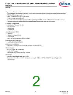
Functional overview
1
Functional overview
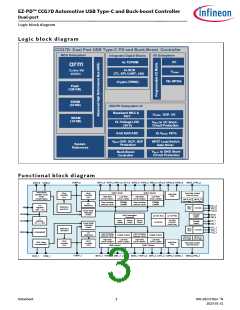
MCU subsystem
CPU
1.1
1.1.1
The Cortex®-M0 in CCG7D devices is a 32-bit MCU, which is optimized for low-power operation with extensive
clock gating. It mostly uses 16-bit instructions and executes a subset of the Thumb-2 instruction set. It also
includes a hardware multiplier, which provides a 32-bit result in one cycle. It includes an interrupt controller (the
NVIC block) with 32 interrupt inputs and a wakeup interrupt controller (WIC), which can wake the processor up
from Deep Sleep mode.
1.1.2
Flash ROM and SRAM
CCG7D devices have 128-KB Flash and 32-KB ROM for non-volatile storage. ROM stores libraries for authentication
and device drivers such as I2C, SPI, and so on. That spares flash for user application. Flash provides the flexibility
to store code for any customer feature and allows firmware upgrades to meet the latest USB-PD specifications
and application needs.
The 16-KB RAM is used under software control to store the temporary status of system variables and parameters.
A supervisory ROM that contains boot and configuration routines is provided.
1.2
USB-PD subsystem
This subsystem provides the interface to the Type-C USB port. This subsystem comprises:
• USB-PD physical layer
• VCONN switches and 100 mW VCONN source
• UVP, OVP on VBUS
• Output high-side current sense amplifier (CSA) for VBUS
• VBUS discharge control
• Gate driver for VBUS provider NFET
• Charger detection block for legacy charging (for example: BC1.2, Apple charging, and so on)
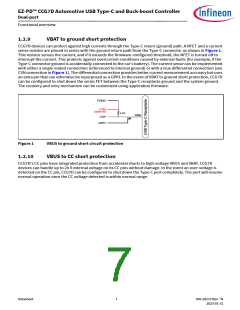
• VBAT to ground short-circuit protection
• VBUS to CC short-circuit protection
1.2.1
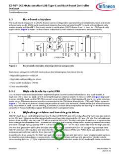
USB-PD physical layer
The USB-PD subsystem contains the USB-PD physical layer block and supporting circuits. The USB-PD physical
layer consists of a transmitter and receiver that communicate BMC encoded data over the CC channel per the
PD 3.1 standard. All communication is half-duplex. The physical layer or PHY implements collision avoidance to
minimize communication errors on the channel.
The USB-PD block includes all termination resistors (Rp and Rd) and their switches as required by the USB Type-C
spec. Rp and Rd resistors are required to implement connection detection, plug orientation detection and for the
establishment of the USB source/sink roles. The Rp resistor is implemented as a current source.
CCG7D device family with accompanying firmware is fully complaint with revisions 3.1 and 2.0 of the USB-PD
specification. The device supports PPS operation at all valid voltages from 3.3 to 21 V.
CCG7D devices support Rp under HW control in unconnected (standby) state to minimize standby power.
CCG7D devices support USB-PD Extended Messages containing data of up to 260 bytes. The extended messages
are larger than expected by USB-PD 2.0 hardware. As per the USB-PD protocol specification, devices compliant
with USB-PD revision 3.0 and later implement a chunking mechanism; messages are limited to Revision 2.0 sizes
unless both source and sink confirm and negotiate compatibility with longer message lengths.
Datasheet
5
002-28172 Rev. *N
2023-01-31

 INFINEON [ Infineon ]