EZ-PD™ CCG7D Automotive USB Type-C and Buck-boost Controller
Dual-port
CCG7D programming and bootloading
4
CCG7D programming and bootloading
There are two ways to program application firmware into a CCG7D device:
1. Programming the device flash over SWD interface
2. Application firmware update over specific interfaces (CC, I2C)
Generally, the CCG7D devices are programmed over SWD interface only during development or during the
manufacturing process of the end-product. Once the end-product is manufactured, the CCG7D device’s
application firmware can be updated via the appropriate bootloader interface. Infineon strongly recommends
customers to use the EZ-PD Configuration Utility to turn off the application firmware update over CC or I2C
interface in the firmware that is updated into CCG7D’s flash before mass production. This prevents unauthorized
firmware from being updated over CC interface in the field. If you desire to retain the application firmware update
over CC/ I2C interfaces feature post-production for on-field firmware updates, contact Infineon Sales for further
guidelines.
4.1
Programming the device flash over SWD interface
The CCG7D family of devices can be programmed using the SWD interface. Infineon provides programming kits
(CY8CKIT-002 MiniProg3 Kit) called MiniProg3 and (CY8CKIT-005 MiniProg4 Kit) MiniProg4 which can be used
to program the flash as well as debug firmware. The flash is programmed by downloading the information from
a hex file. This hex file is a binary file generated as an output of building the firmware project in PSoC™ Creator
Software. Click here for more information on how to use the MiniProg3 programmer. Click here for more
information on how to use the MiniProg4 programmer. There are many third-party programmers that support
mass programming in a manufacturing environment.
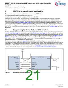
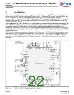
As shown in the block diagram in Figure 10, the SWD_DAT and SWD_CLK pins are connected to the host
programmer’s SWDIO (data) and SWDCLK (clock) pins respectively. During SWD programming, the device can be
powered by the host programmer by connecting its VTARG (power supply to the target device) to VDDD pins of
CCG7D device. If the CCG7D device is powered using an on-board power supply, it can be programmed using the
“Reset Programming” option. For more details, refer the CYPDXXXX Programming Specifications.
3.3 V
VDD
Host Programmer
VTARG
CYPD7XXX
VDDD
VDDD
10µF
1µF
0.1µF
0.1µF
SWDCLK
SWDIO
XRES
SWD_CLK
SWD_DAT
XRES
VCCD
0.1µF
GND
GND
GND
Figure 10
Connecting the programmer to CYPD7XXX device
Datasheet
21
002-28172 Rev. *N
2023-01-31

 INFINEON [ Infineon ]